Control knob with multiple degrees of freedom and force feedback

a technology of force feedback and control knob, which is applied in the direction of mechanical control devices, manual control with single controlling member, instruments, etc., can solve the problems of limited control options of users, limited control functionality of knobs, and limited user control options, so as to achieve the effect of providing more control over desired functions and fully taking advantage of force feedback

Inactive Publication Date: 2007-06-19
IMMERSION CORPORATION
View PDF5 Cites 81 Cited by
  • Summary
  • Abstract
  • Description
  • Claims
  • Application Information

AI Technical Summary

Benefits of technology

[0006]The present invention provides a knob control interface that allows a user to control functions of a device in a variety of ways. Embodiments of the knob controller include additional degrees of freedom for the knob and force feedback applied to the knob.

Problems solved by technology

One problem occurring in control knobs of the prior art is that the knobs are limited to basic rotary motion.
This limits the control options of the user to a simple, one-degree-of-freedom device that does not allow a variety of selection options.
In additions if force feedback is provided on the knob, the limited control functionality of the knob limits the user from fully taking advantage of the force feedback to provide more control over desired functions.

Method used


Image

  • Control knob with multiple degrees of freedom and force feedback
  • Control knob with multiple degrees of freedom and force feedback
  • Control knob with multiple degrees of freedom and force feedback

Examples


Embodiment Construction

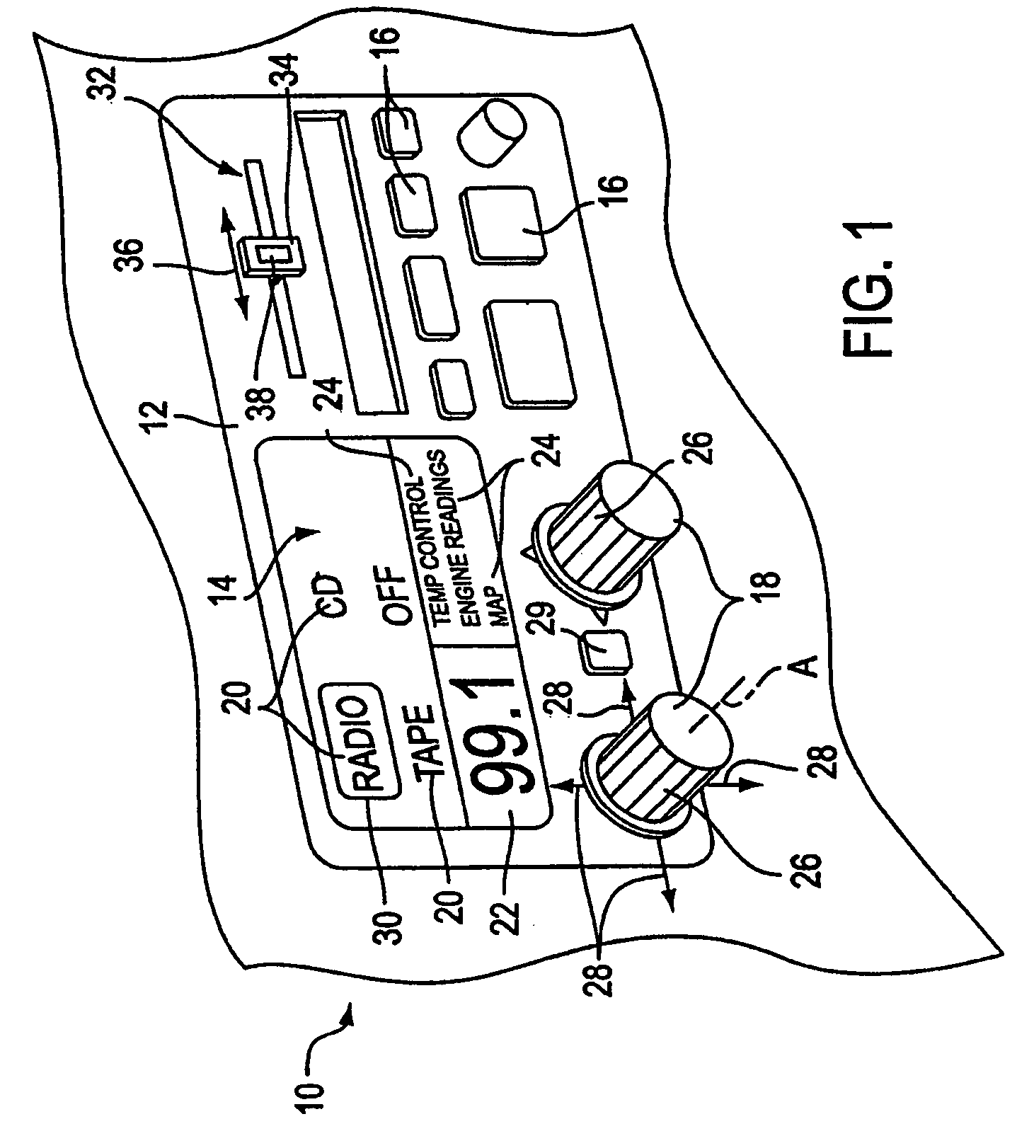
[0025]FIG. 1 is a perspective view of an example of a control panel 12 for a device 10 including a control knob of the present invention. In the described embodiment, device 10 is an audio device that controls the output of sound, such as music or speech, from speakers that are connected to the device 10. For example, a common embodiment of device 10 is a stereo system that includes the ability to play sound from one or more media or signals, such as cassette tapes, digital audio transmission (DAT) tapes, compact discs (CD's) or other optical discs, or radio signals transmitted through the air from a broadcasting station.

[0026]The device 10 can also include additional or other functionality not related to audio control and output. For example, many vehicles include electronic systems to control the temperature in the vehicle cabin (air conditioning, heat, etc.), as well as systems to provide information on the current operating characteristics of the vehicle, such as current speed, ...


PUM


Abstract

The present invention provides a control knob on a device that allows a user to control functions of the device. In one embodiment, the knob is rotatable in a rotary degree of freedom and moveable in at least one transverse direction approximately perpendicular to the axis. An actuator is coupled to the knob to output a force in the rotary degree of freedom about the axis, thus providing force feedback. In a different embodiment, the knob is provided with force feedback in a rotary degree of freedom about an axis and is also moveable in a linear degree of freedom approximately parallel to the axis, allowing the knob to be pushed and/or pulled by the user. The device controlled by the knob can be a variety of types of devices, such as an audio device, video device, etc. The device can also include a display providing an image updated in response to manipulation of the knob. Detent forces can be provided for the knob by overlapping and adjusting ranges of closely-spaced detents in the rotary degree of freedom of the knob.

Description

CROSS-REFERENCE TO RELATED APPLICATIONS[0001]This application claims the benefit of and is a continuation of U.S. application Ser. No. 09 / 680,408, filed Oct. 2, 2000, now U.S. Pat. No. 6,686,911, which is a continuation of U.S. application Ser. No. 09 / 179,382, filed on Oct. 26, 1998, now U.S. Pat. No. 6,154,201, which is a continuation-in-part of U.S. application Ser. No. 09 / 049,155, filed Mar. 26, 1998, now U.S. Pat. No. 6,128,006, and U.S. application Ser. No. 09 / 087,022, filed May 29, 1998, now U.S. Pat. No. 6,061,004, which is a divisional of U.S. application Ser. No. 08 / 756,745, now U.S. Pat. No. 5,825,308, filed Nov. 26, 1996, each of which is assigned to the assignee of the present application, and each of which is incorporated in its entirety herein by reference.BACKGROUND OF THE INVENTION[0002]This invention relates generally to knob control devices, and more particularly to control knob devices including force feedback and additional input functionality.[0003]Control knobs...

Claims


Application Information

Patent Timeline
Patent Type & Authority Patents(United States)
IPC IPC(8): G09G5/00G09G5/08G05G9/047G06F3/00G06F3/01G06F3/023G06F3/039
CPCG06F3/016G06F3/0219G06F3/0354G06F3/0362G06F3/0395G06F3/0482G05G9/047A63F2300/1037Y10T74/20201G05G2009/0477G06F2203/013G06F2203/014H01H2003/008Y10S715/97Y10S715/974
Inventor LEVIN, MICHAEL D.MARTIN, KENNETH M.SCHENA, BRUCE M.BRAUN, ADAM C.ROSENBERG, LOUIS B.
Owner IMMERSION CORPORATION
Why Eureka
Try Eureka