Apparatus and method for determining an absolute pose of a manipulated object in a real three-dimensional environment with invariant features

a technology of invariant features and manipulated objects, applied in the field of determining the absolute pose of manipulated objects in a real three-dimensional environment with invariant features, can solve the problems of not having a sufficiently robust and rapid absolute pose determination system, many do not even provide absolute pose determination, and it is not possible to achieve one-to-one motion mapping between space and cyberspace. , the effect of high optical contras

Inactive Publication Date: 2010-01-07
ELECTRONICS SCRIPTING PRODS
View PDF99 Cites 80 Cited by
  • Summary
  • Abstract
  • Description
  • Claims
  • Application Information

AI Technical Summary

Benefits of technology

[0023]It is the object of the present invention to introduce a particularly effective optical navigation apparatus and methods for optically inferring or measuring the absolute pose of objects manipulated in real three-dimensional environments. More particularly, it is an objective of the present invention to address manipulated objects such as hand-held devices moved directly by a human user in close-range, real three-dimensional environments including constrained environments, living quarters and work-spaces. The numerous objects and advantages of the apparatus and method of invention will become apparent upon reading the ensuing description in conjunction with the appended drawing figures.
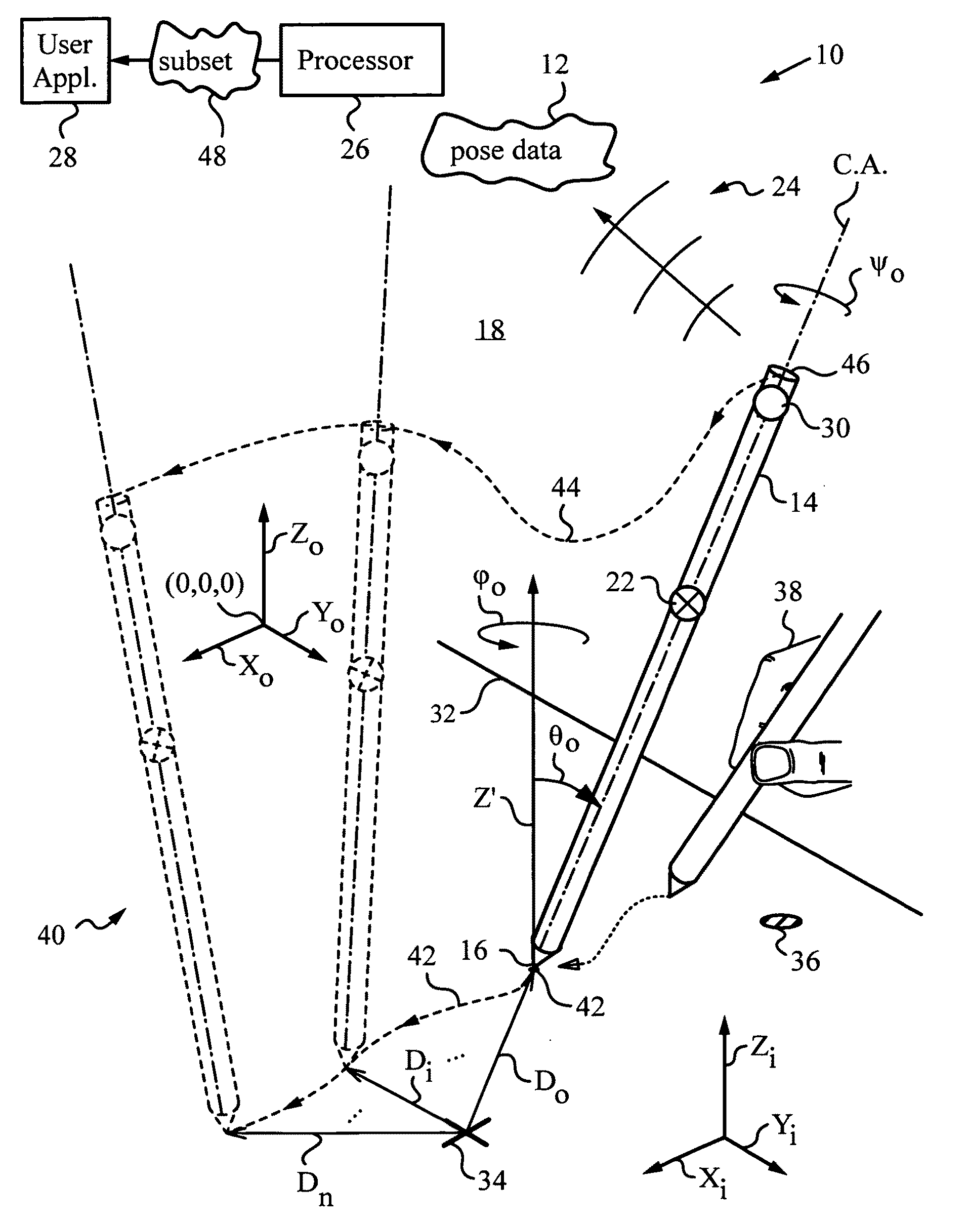
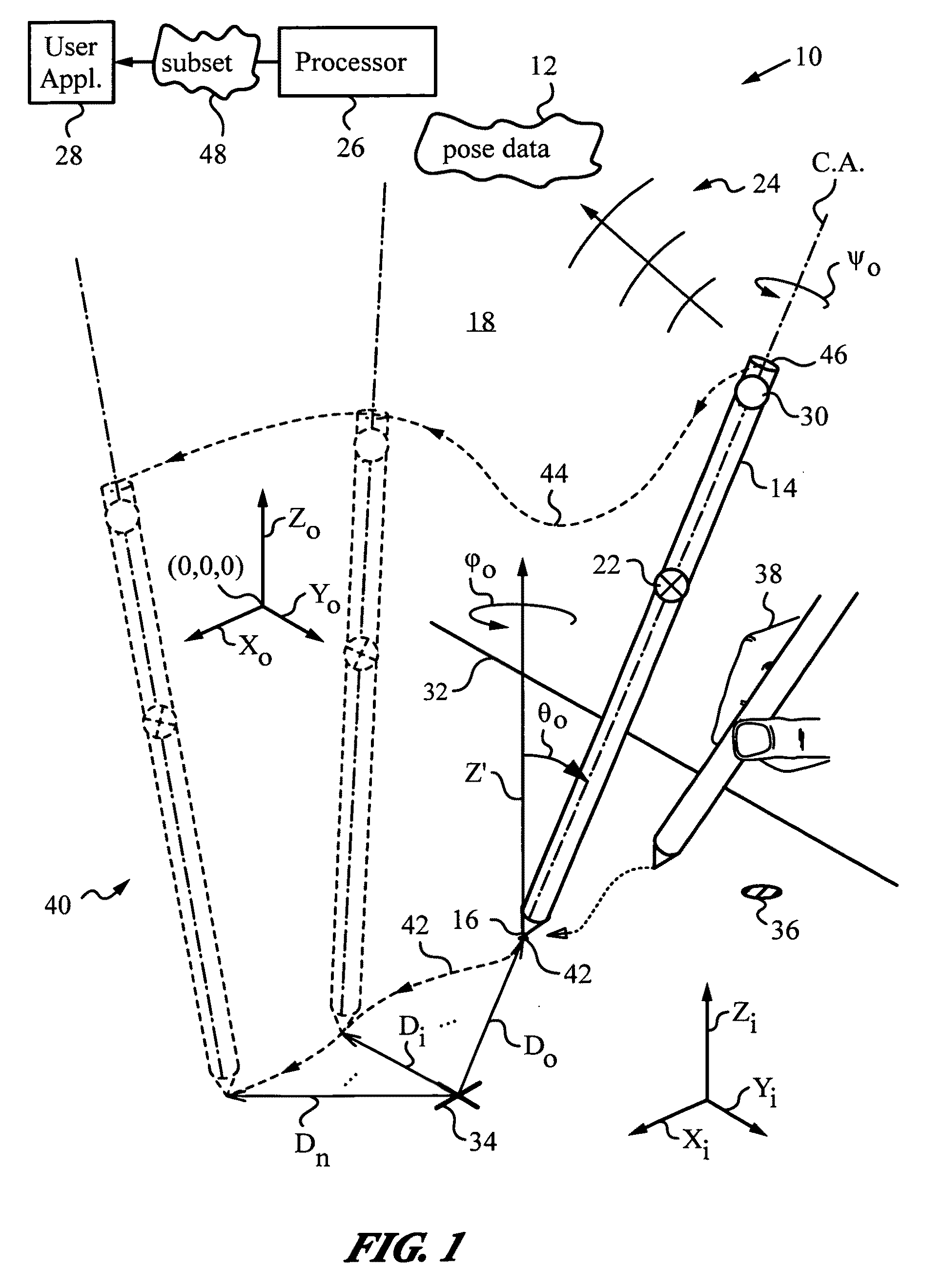
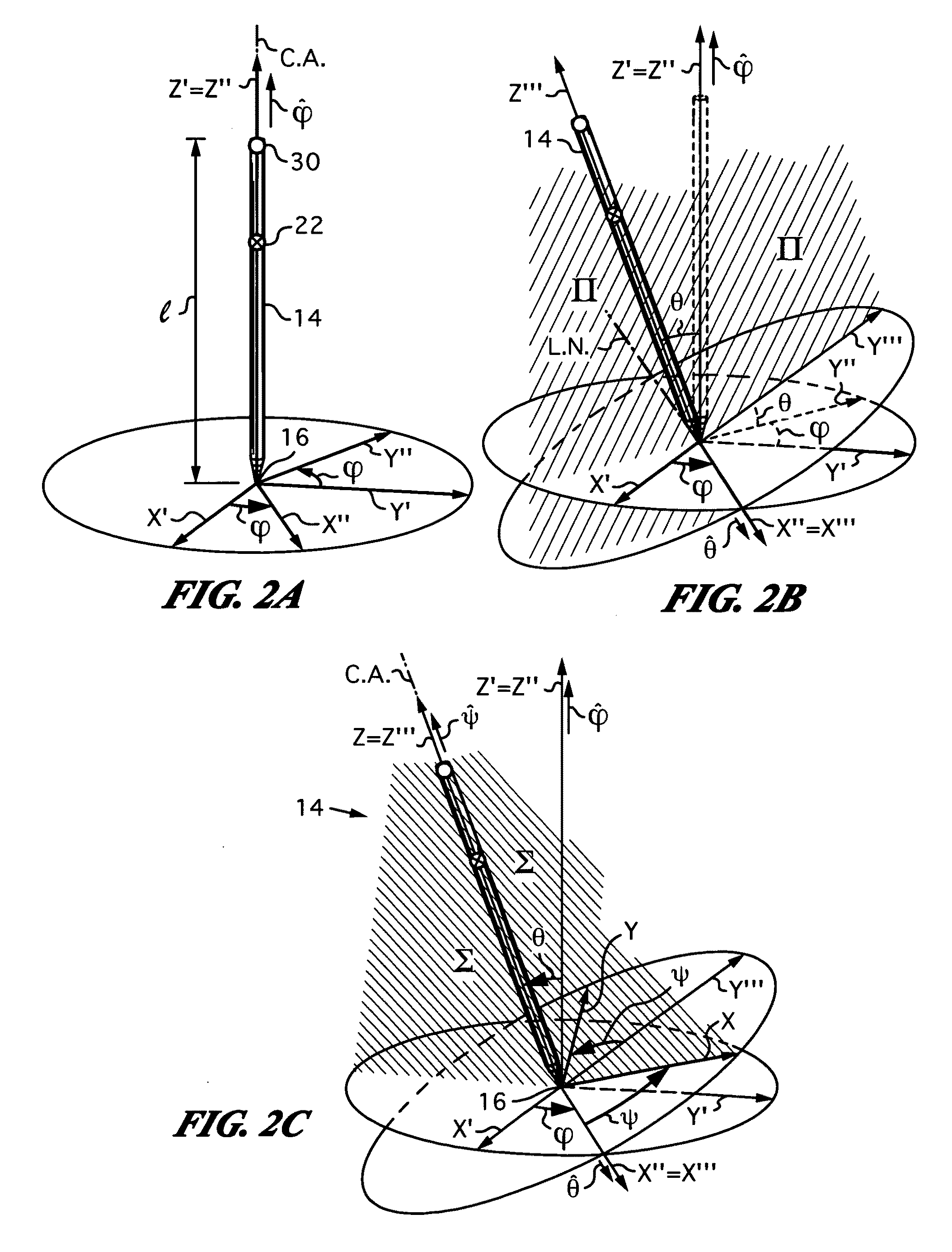
[0024]The objects and advantages of the present invention are accomplished by an optical apparatus and by an optical method that work with an absolute pose of a manipulated object. Specifically, the apparatus is designed for processing absolute pose data derived from the absolute pose of the manipulated object that exists and moves in a real three-dimensional environment. The apparatus has at least one invariant feature that is placed in the real three-dimensional environment. An optical measuring arrangement is provided on-board the manipulated object for optically inferring the absolute pose from on-board the object using the one or more invariant features. The inferred absolute pose is expressed with absolute pose data (φ,θ,ψ,x,y,z) that represents Euler rotated object coordinates expressed in world coordinates (Xo,Yo,Zo) with respect to a reference location. In other words, the apparatus works with all six degrees of freedom (three translational degrees of freedom and three rotational degrees of freedom) available to objects moving in real three-dimensional space. Furthermore, the apparatus is equipped with a processor for preparing the absolute pose data and identifying a subset of the absolute pose data. In the most general case, the subset may contain all absolute pose -data corresponding to the complete absolute pose that was optically inferred. The apparatus employs a communication link, such as a wireless communication link, for transmitting the subset to an application.
[0025]The apparatus of invention may use any convenient location, whether corresponding to the position of an actual item or entity in real space or not, as a reference location. Advantageously, the reference location is selected to be a world origin (0,0,0) of the world coordinates (Xo,Yo,Zo). Furthermore, the one or more invariant features preferably include among them one or several high optical contrast features. Indeed, it is even more preferable that the one or more high optical contrast features be constituted by light sources. Suitable light sources include, but are not limited to screens, display pixels, fiber optical waveguides and light-emitting diodes. Among the latter, infrared emitting diodes or IR LEDs are preferred. Alternatively, the high optical contrast feature or features can be reflectors or retro-reflectors.
[0026]In some embodiments the application has an output that is displayed to a user or users who may or may not be handling the manipulated object. In these embodiments the subset includes the input for interacting with the application's output. For example, in some embodiments the output has one or more visual elements such as images, graphics, text or icons. The apparatus has a display such as a display screen or a projection display for displaying the visual elements to the user. In one very specific embodiment, the display is a touch sensitive display that allows the user to also interact with the output via touch and multi-touch gestures.
[0027]Alternatively or in addition, the same or different embodiments may include audio elements in the application's output. These audio elements can be tones, tunes, musical compositions and alert signals. In embodiments where the output includes audio elements the apparatus has speakers for playing the audio elements to the user.
[0028]In some embodiments the optical measuring arrangement has a light-measuring component equipped with a lens and an optical sensor. For example, the lens can be an imaging lens for imaging the three-dimensional environment and the optical sensor can be a photodetector for sensing light arriving from the one or more invariant features. Specifically, the photodetector can be a pixel array sensor, e.g., a CMOS, a CCD or a PIN-diode sensor. In cases where the apparatus employs one or more predetermined light sources and these light sources act as beacons (i.e., they are distinguishable) the photodetector can be a position-sensing device (PSD) that directly determines a centroid of light flux from the light source or sources. To avoid ambient illumination interference, it is preferable that the light sources be constituted by a number of infrared emitting diodes or IR LEDs in such embodiments. In addition, the IR LEDs can be modulated in a certain pattern to further improve their signal-to-noise performance and render them better distinguishable, i.e., improving their functioning as beacons.

Problems solved by technology

A major problem encountered by state of the art manipulated objects such as control wands and gaming implements is that they do not possess a sufficiently robust and rapid absolute pose determination system.
In fact, many do not even provide for absolute pose determination.
Unfortunately, one-to-one motion mapping between space and cyberspace is not possible without the ability to digitize the absolute pose of the manipulated object with respect to a well-defined reference location in real space.
All prior art devices that do not solve the full motion problem, i.e., do not capture successive poses of the manipulated object with a method that accounts for all six degrees of freedom (namely, the very parameters (x,y,z,φ,θ,ψ) inherent in three-dimensional space) encounter limitations.
Among many others, these include information loss, appearance of an offset, position aliasing, gradual drift and accumulating position error.
In general, motion capture tends to be computationally expensive because of significant image pre- and post-processing requirements, as well as additional computation associated with segmentation and implementation of algorithms.
The above approaches using markers on objects and cameras in the environment to recover object position, orientation or trajectory are still too resource-intensive for low-cost and low-bandwidth applications.
This is due to the large bandwidth needed to transmit image data captured by cameras, the computational cost to the host computer associated with processing image data, and the data network complexity due to the spatially complicated distribution of equipment (i.e., placement and coordination of several cameras in the environment with the central processing unit and overall system synchronization).
Unfortunately, approaches in which multiple cameras are set up at different locations in the three-dimensional environment to enable stereo vision defy low-cost implementation.
These solutions also require extensive calibration and synchronization of the cameras.
Meanwhile, the use of expensive single cameras with depth sensing does not provide for robust systems.
The resolution of such systems tends to be lower than desired, especially when the user is executing rapid and intricate movements with the manipulated object in a confined or close-range environment.
Unfortunately, the complexity of additional hardware for projecting images with characteristic image points is nontrivial.
The same is true of consequent calibration and interaction problems, including knowledge of the exact location of the image in three-dimensional space.
This solution is not applicable to close-range and / or confined environments, and especially environments with typical obstructions that interfere with line-of-sight conditions.

Method used


Image

  • Apparatus and method for determining an absolute pose of a manipulated object in a real three-dimensional environment with invariant features
  • Apparatus and method for determining an absolute pose of a manipulated object in a real three-dimensional environment with invariant features
  • Apparatus and method for determining an absolute pose of a manipulated object in a real three-dimensional environment with invariant features

Examples


Embodiment Construction

[0069]To appreciate the basic aspects of the present invention, we initially turn to a simple version of an apparatus 10 in accordance with the invention, as shown in FIG. 1. Apparatus 10 has a manipulated object 14 whose motion 40 in a real three-dimensional environment 18 is expressed by absolute pose data 12. Apparatus 10 processes absolute pose data 12 that describe the absolute pose of manipulated object 14 at a number of measurement times ti. Thus, successive pose data 12 collected at the chosen measurement times describe the motion that manipulated object 14 executes or is made to execute by a user 38.

[0070]Manipulated object 14 is any object that is moved either directly or indirectly by a user 38 and whose pose when object 14 is stationary or in motion yields useful absolute pose data 12. For example, manipulated object 14 is a pointer, a wand, a remote control, a three-dimensional mouse, a game control, a gaming object, a jotting implement, a surgical implement, a three-di...


PUM


Abstract

An apparatus and method for optically inferring an absolute pose of a manipulated object in a real three-dimensional environment from on-board the object with the aid of an on-board optical measuring arrangement. At least one invariant feature located in the environment is used by the arrangement for inferring the absolute pose. The inferred absolute pose is expressed with absolute pose data (φ,θ,ψ,x,y,z) that represents Euler rotated object coordinates expressed in world coordinates (Xo,Yo,Zo) with respect to a reference location, such as, for example, the world origin. Other conventions for expressing absolute pose data in three-dimensional space and representing all six degrees of freedom (three translational degrees of freedom and three rotational degrees of freedom) are also supported. Irrespective of format, a processor prepares the absolute pose data and identifies a subset that may contain all or fewer than all absolute pose parameters. This subset is transmitted to an application via a communication link, where it is treated as input that allows a user of the manipulated object to interact with the application and its output.

Description

RELATED APPLICATIONS[0001]This application is a continuation-in-part application of U.S. patent application Ser. No. 11 / 591,403 filed on Oct. 31, 2006 and claiming priority from U.S. Provisional Patent Application No. 60 / 780,937 filed on Mar. 8, 2006, and further of U.S. patent application Ser. No. 10 / 769,484 filed on Jan. 30, 2004, all incorporated herein in their entirety.FIELD OF THE INVENTION[0002]The present invention relates generally to determining an absolute pose of a manipulated object in a real three-dimensional environment with invariant features, and it applies in particular to manipulated objects used by human users to interface with the digital world.BACKGROUND OF THE INVENTION[0003]An object's pose in a real three-dimensional environment can be expressed with respect to stationary references such as ground planes, reference surfaces, lines, solids, fixed points and other invariant features disposed in the real three-dimensional environment. It is convenient to parame...

Claims


Application Information

Patent Timeline
Patent Type & Authority Applications(United States)
IPC IPC(8): G06T15/00G06F3/041
CPCG01B11/002G01B11/03G06F3/0325G06T7/0042G06F3/03545G06F3/04815G06K9/22G06F3/0346G06T7/73G06V10/17
Inventor MANDELLA, MICHAEL J.GONZALEZ-BANOS, HECTOR H.ALBOSZTA, MAREK
Owner ELECTRONICS SCRIPTING PRODS
Why Eureka
Try Eureka