Eureka AIR delivers breakthrough ideas for toughest innovation challenges, trusted by R&D personnel around the world.

Simple paste for measuring surface deformation of material and production method thereof

A surface deformation and simple technology, applied in the direction of measuring devices, chemical instruments and methods, instruments, etc., can solve the problems of less grid/lattice, large grid/lattice size, smaller size, etc., to improve the processing speed. And the effect of precision, mature production technology, and short production cycle

Inactive Publication Date: 2013-08-28
UNIV OF SCI & TECH OF CHINA
View PDF0 Cites 1 Cited by
  • Summary
  • Abstract
  • Description
  • Claims
  • Application Information

AI Technical Summary

Problems solved by technology

[0010] The size of the grid / dot matrix produced by the above technology is often large, and it is difficult to ensure the production accuracy. Although the larger grid / dot matrix can improve the measurement accuracy, but the grid / dot matrix is ​​too large, the CCD camera There will be too few grids / lattices in the field of view, resulting in insufficient data volume, so the diameter of the grid / lattice should be the smallest size that does not affect the measurement accuracy
Moreover, with the development of high-resolution CCD cameras, the size of the grid / dot matrix that the camera itself can distinguish becomes smaller, and even a grid / dot matrix with a diameter of 100 microns and a pitch of 300 microns can be resolved. The size of the grid / dot matrix obtained by the second to fifth grid and lattice production methods is too large, which can no longer meet the needs of high-resolution CCD cameras.

Method used


Image

  • Simple paste for measuring surface deformation of material and production method thereof
  • Simple paste for measuring surface deformation of material and production method thereof
  • Simple paste for measuring surface deformation of material and production method thereof

Examples


Embodiment 1

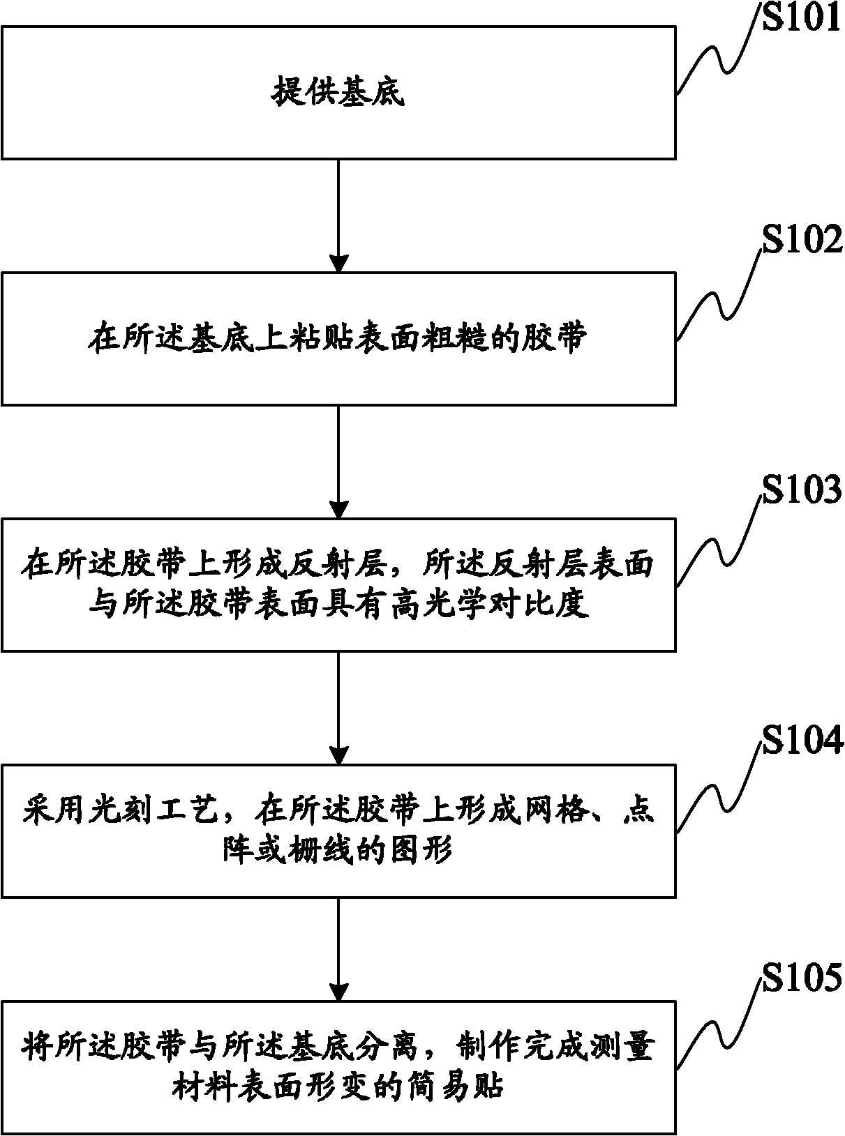
[0058] This embodiment discloses a method for making a simple sticker for measuring the surface deformation of a material. The flow chart of the method is as follows figure 2 As shown, the cross-sectional diagram of each step of the method is shown in Figure 3-Figure 9 shown, including the following steps:

[0059] Step S101: providing a substrate 11;

[0060] see image 3 , the main function of the base 11 is to make the surface of the adhesive tape to be pasted smooth, so as to make grid / dot matrix etc. on the surface of the adhesive tape. Therefore, the base 11 only needs to be a flat base. Planar glass substrate, of course, other planar substrates can also be used.

[0061] Step S102: Paste an adhesive tape 12 with a rough surface on the base 11, such as image 3 shown;

[0062] The side of the adhesive tape 12 that is in contact with the base 11 can have adhesive or the like, so that after the adhesive tape 12 is laid flat, it can be pasted together with the base 1...

Embodiment 2

[0079] The flow chart of the method for making the simple sticker for measuring the surface deformation of the material disclosed in this embodiment is as follows Figure 10 As shown, the cross-sectional diagram of each step is shown in Figure 3-Figure 9 As shown, the difference between this embodiment and the previous embodiment is that step S205 is added on the basis of the previous embodiment: after removing the photoresist, on the adhesive tape with the pattern of grid, dot matrix or grid line Form protective layer 15, to avoid that the figure of described grid, dot matrix or grid line comes off, as Figure 9 shown.

[0080] Specifically, the chrome grid / dot matrix can be fixed on the PVC tape by spraying transparent paint on the PVC tape with chrome lattice, so as to avoid the chrome grid / dot matrix under external friction during use. The thickness of the transparent paint is about 10nm, and the thickness should be uniform, so as not to affect the measurement results. ...

Embodiment 3

[0094] Corresponding to the above method embodiments, this embodiment discloses a simple sticker for measuring the surface deformation of a material made by using the methods of the above two embodiments. The simple sticker includes:

[0095] A tape with a rough surface, preferably a PVC tape with a black surface;

[0096] The pattern of the grid, dot matrix or grid line arranged on the adhesive tape, the graphic surface of the grid, dot matrix or grid line has high optical contrast with the surface of the adhesive tape, and the grid, dot matrix or grid line The production of graphics such as lines is preferably metallic chrome.

[0097] In addition, the simple sticker also includes a protective layer covering the graphics of the grid, dot matrix or grid lines, preferably transparent paint, so as to prevent the graphics of the grid, dot matrix or grid lines from falling off under external friction.

[0098] In this embodiment, the simple sticker consisting of PVC tape and chr...


PUM

PropertyMeasurementUnit
thicknessaaaaaaaaaa

Abstract

The embodiment of the invention discloses a simple paste for measuring the surface deformation of a material and a production method thereof. The method comprises the following steps of: providing a substrate; sticking an adhesive tape with a coarse surface onto the substrate; forming a reflecting layer on the adhesive tape, wherein the surface of the reflecting layer and the surface of the adhesive tape have high optical contrast ratios; forming graphs of grids, dot matrixes or grid lines on the adhesive tape by adopting a photoetching process; and separating the adhesive tape from the substrate, thus the simple paste for measuring the surface deformation of the material is obtained. In the embodiment of the invention, the grids, dot matrixes or grid lines with the diameter in micron or millimetre can be obtained by adopting the photoetching process, thus the dimension of a final grid / dot matrix can meet the requirements of a CCD (charge coupled device) camera and an automatic grid method to small-dimension grids / dot matrixes. Meanwhile, the characteristics of an ultraviolet photoetching technology cause the produced grids, dot matrixes or grid lines to be regular and uniform, the production technology is mature and simple, and the production period is short.

Description

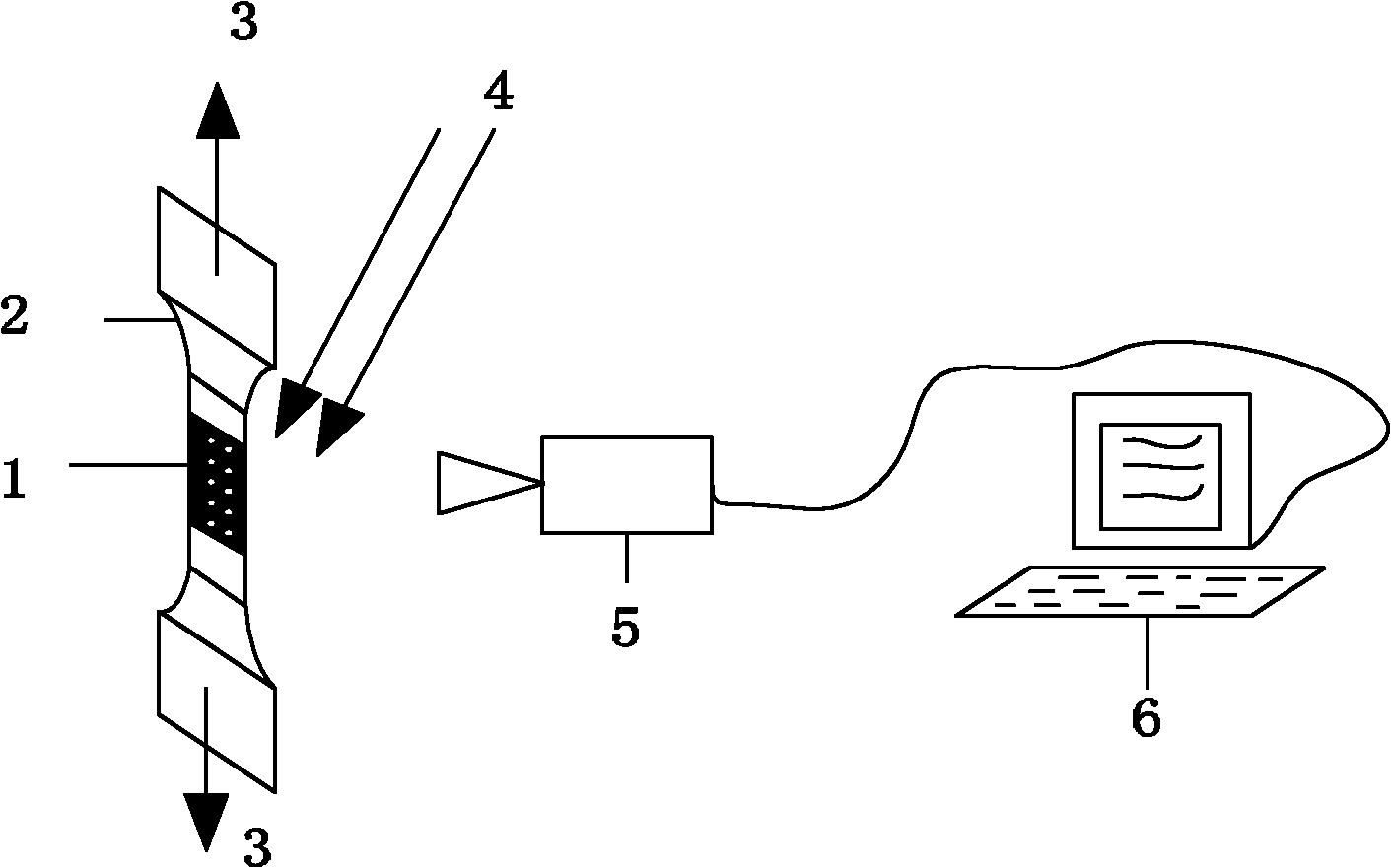
technical field [0001] The invention relates to the technical field of material surface deformation measurement in experimental mechanics, in particular to a simple sticker for measuring material surface deformation and a manufacturing method thereof. Background technique [0002] The in-plane displacement and deformation measurement of the object surface in experimental mechanics mainly includes mechanical method, electrical measurement method and optical measurement method. Among them, the optical measurement method is widely used as a full-field non-contact measurement method. The optical measurement methods that appeared successively in the last century mainly include single-beam speckle imaging method, planar moiré method, moiré interferometry, electronic speckle interferometry, digital speckle correlation technology and automatic grid method. The automatic grid method prefabricates an orthogonal grid or an orthogonal lattice on the object, records two grid images befor...

Claims


Application Information

Patent Timeline
Patent Type & Authority Patents(China)
IPC IPC(8): B32B3/30B32B17/10B32B15/082G01B11/16G01B11/02
Inventor 邱克强刘正坤徐向东刘颖洪义麟付绍军
Owner UNIV OF SCI & TECH OF CHINA
Why Eureka
Eureka Blog
Learn More