
Automatic card dispensing unit with display capability

Inactive Publication Date: 2005-09-06
ASAHI SEIKO CO LTD
View PDF15 Cites 15 Cited by
  • Summary
  • Abstract
  • Description
  • Claims
  • Application Information

AI Technical Summary

Benefits of technology

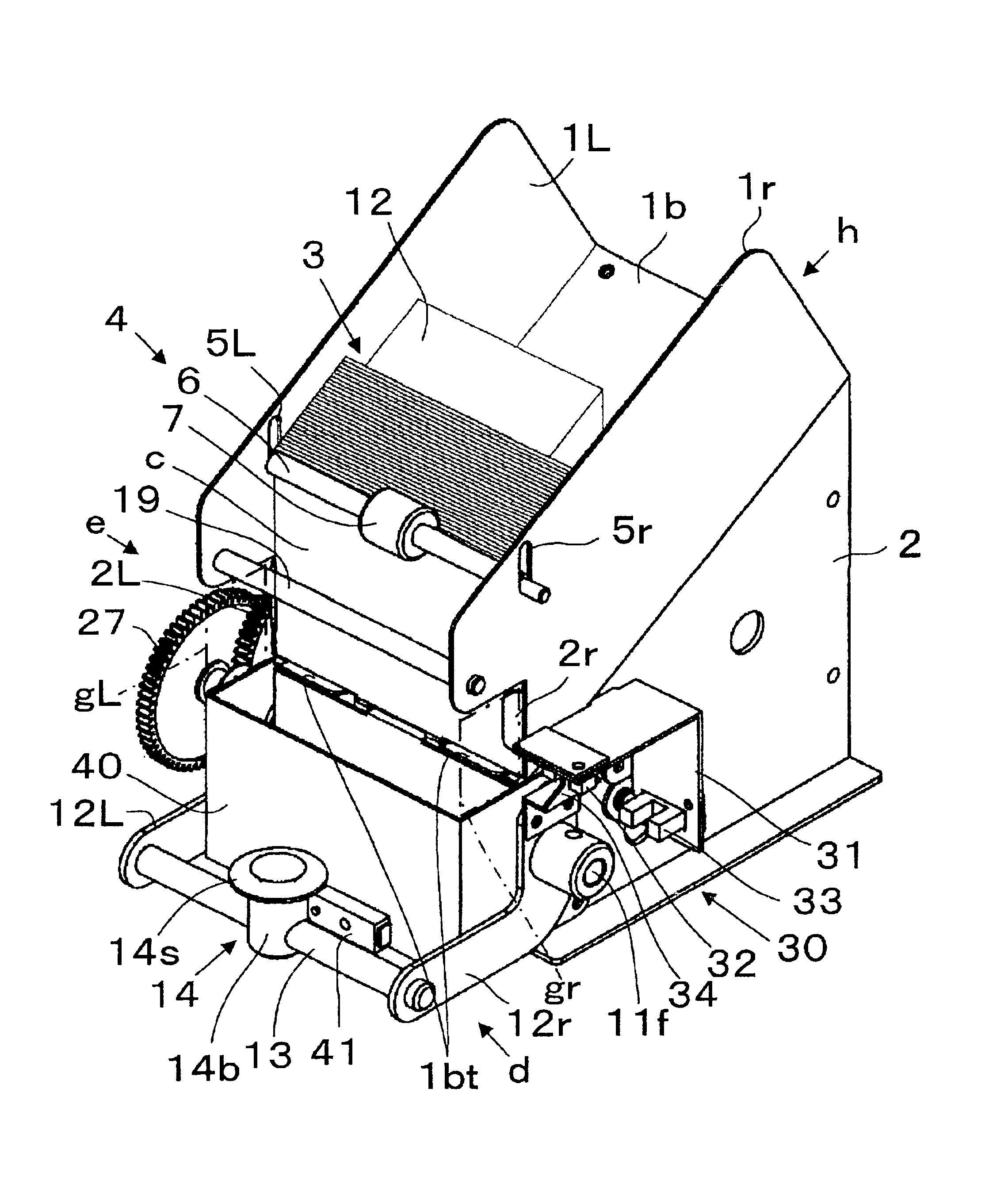
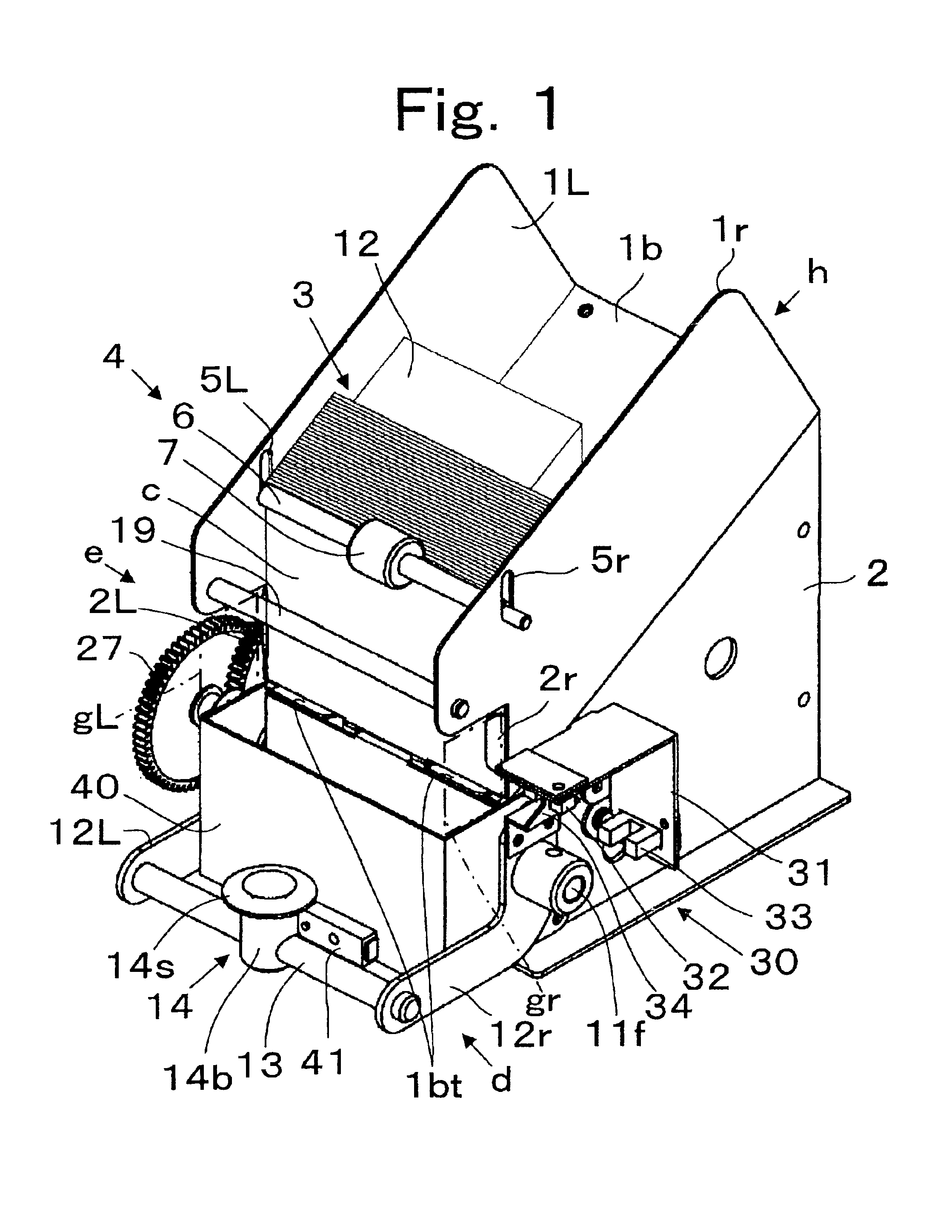
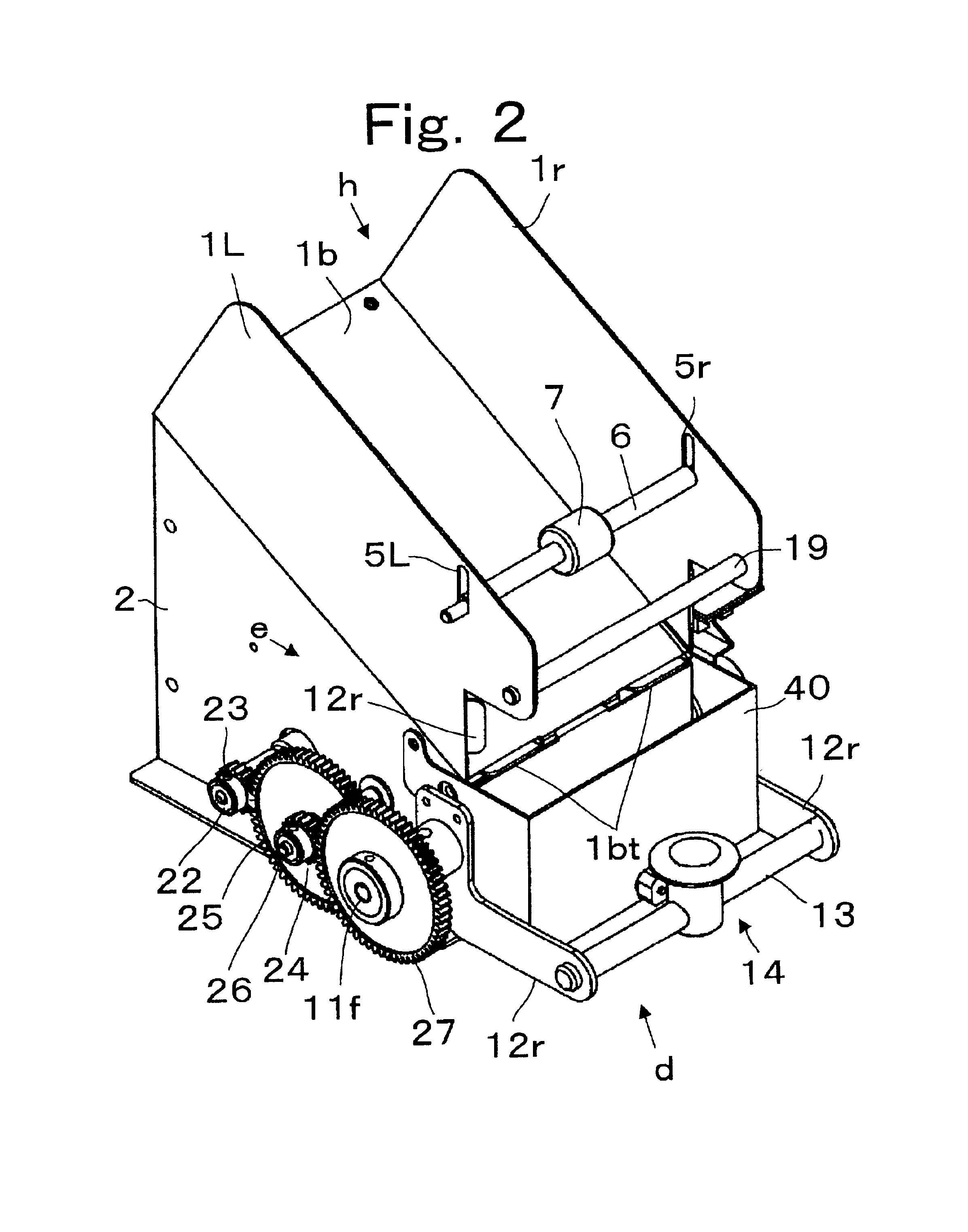
[0008]An automatic card dispenser unit for displaying and dispensing cards is provided. The automatic card dispensing unit can be integrated into a vending machine or can be a modular unit that is adaptable for installing within a vending machine having an appropriate window to permit the display of cards. A storage housing can store a plurality of cards preferably in a vertical alignment in such a manner that may be urged in an array environment to a display position against a holding member that can position one of the plurality of cards for both display and at a loading position for dispensing. The automatic card dispensing unit can incorporate a micro processor based controller unit that can receive a user input to dispense a card and control a dispenser assembly wherein a motor can drive a pickup member to removable grasp the card surface at the loading position and to subsequently release it along a predetermined path of movement for dispensing to the user. Appropriate sensors can monitor the dispenser assembly while a stopper member can be mounted in a path of movement for separating a card from a pickup member to enable the card to be dispensed to the user. The stopper member is preferably transparent to facilitate the display of the card to the user and can further include a friction material to insure a positive release from the pickup device.
[0009]The controller unit can monitor the operation of the automatic card dispenser unit and can initiate a subsequent activation if the initial activation does not release a card. The controller unit can further indicate an error signal if the card dispenser unit malfunctions. Finally, the pickup member can mechanically capture and release a suspended card to insure an economical design.

Problems solved by technology

As labor costs have increased various forms of dispensing apparatus have been employed to automatically dispense items to users.

Method used


Image

  • Automatic card dispensing unit with display capability
  • Automatic card dispensing unit with display capability
  • Automatic card dispensing unit with display capability

Examples


Embodiment Construction

[0019]The following description is provided to enable any person skilled in the art to make and use the invention, and sets forth the best modes contemplated by the inventor of carrying out his invention. Various modifications, however, will remain readily apparent to those skilled in the art, since the general principles of the present invention have been defined herein specifically to provide a machine for dispensing articles from a stack and displaying the same.

[0020]In the present invention the terminology card is used to describe the stacked array of items that are to be dispensed by the present invention. Thus, the term card is not limited to the preferred embodiments disclosed herein, but rather is used as a convenient manner of describing one of an array of objects that can be progressively displayed and dispensed for example, from a vending machine in an economical manner.

[0021]Referring to FIG. 1 a plurality cards, c, can be arrayed within an card holder h so that they can...


PUM


Abstract

An automatic card dispenser unit for displaying and dispensing cards includes a storage housing for storing an array of cards. A holding member operatively positions a lower most card at a load station in a vertical alignment for display. A controller unit can receive a user input to dispense a card which will activate a dispenser assembly to cause a pickup member to removably grasp the card surface and release it from the holding member along a predetermined path of movement. A stopper member is mounted in the path of movement for separating the card from the pickup member to enable the card to be dispense to the user.

Description

BACKGROUND OF THE INVENTION[0001]1. Field of the Invention[0002]Present invention provides an automated card dispensing unit that is capable of displaying a card to a user and dispensing the card upon the request of the user and more particularly for storing a stack of cards for viewing through a display window and for a grasping a surface of a displayed card and releasing it without obstructing the display feature.[0003]2. Description of the Related Art[0004]As labor costs have increased various forms of dispensing apparatus have been employed to automatically dispense items to users. For example, dispensing machines have, upon the insertion of monetary value by a user, dispensed telephone cards, subway tickets, bus tickets, prepaid credit cards, arcade game cards, novelty character cards, etc. Usually, the cards are thin rectangular objects with writing and / or display symbols placed on a face surface of the cards. The cards can be made from various materials such as a resin materi...

Claims


Application Information

Patent Timeline
IPC IPC(8): A63F1/14A63F1/00G07B3/00G07B3/04G07F17/00G07F17/42
CPCA63F1/14G07B3/04G07F17/42
Inventor TSUCHIDA, TAMOTSU
Owner ASAHI SEIKO CO LTD
Learn More