Integrated fuel tank and complementary counterweight

a fuel tank and complementary technology, applied in the direction of tank vehicles, transportation and packaging, transportation items, etc., can solve the problems of increasing the risk of associated leakage, the convenient and secure location of conventional filler tubes, and the inability to conveniently and securely locate them. , to achieve the effect of convenient and secure location, increased risk of leakage, and convenient and secure location

Inactive Publication Date: 2005-09-06
DEERE & CO
View PDF17 Cites 36 Cited by
  • Summary
  • Abstract
  • Description
  • Claims
  • Application Information

AI Technical Summary

Benefits of technology

[0003]The inventors recognize that conventional fuel systems for work vehicles allow fuel tanks to be conveniently and securely located on a work vehicle but significantly increase the risk for leakage with respect to the associated parts due to a relatively large number of connections. They also understand that, frequently, conventional filler tubes are conveniently, but not securely, located in areas that do not minimize the risk of exposure to damage.
[0004]The inventors have solved the above problems by providing a fuel system comprising an integrated fuel tank which includes a fuel tank and a filler tube in a single piece, and a counterweight having a complementary portion that surrounds and protects the filler tube on assembly of the fuel system. This fuel system affords a convenient and secure location for the entire integrated fuel tank, eliminates all connections between the filler tube and the fuel tank and, serendipitously, provides additional counterweight leverage for the work vehicle.

Problems solved by technology

The inventors recognize that conventional fuel systems for work vehicles allow fuel tanks to be conveniently and securely located on a work vehicle but significantly increase the risk for leakage with respect to the associated parts due to a relatively large number of connections.
They also understand that, frequently, conventional filler tubes are conveniently, but not securely, located in areas that do not minimize the risk of exposure to damage.

Method used


Image

  • Integrated fuel tank and complementary counterweight
  • Integrated fuel tank and complementary counterweight
  • Integrated fuel tank and complementary counterweight

Examples


Embodiment Construction

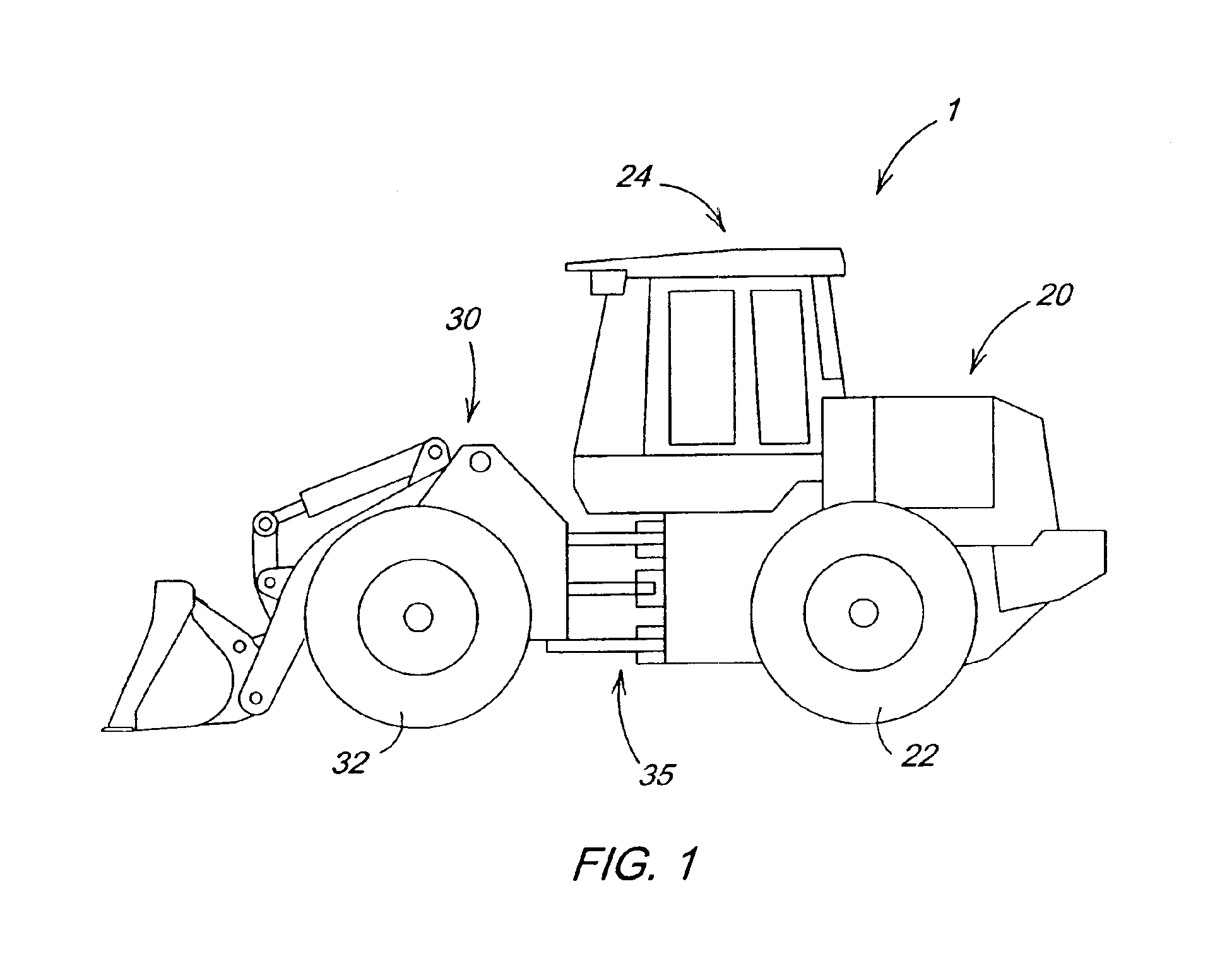
[0016]FIG. 1 illustrates a work vehicle 1 in which the invention may be used. The particular work vehicle illustrated in FIG. 1 is an articulated four wheel drive loader having a body 10 that includes a rear body portion 20 pivotally connected to a front body portion 30 by vertical pivots 35, the loader being steered by pivoting of the front body portion 20 relative to the rear body portion 30 in a manner well known in the art. The rear and front body portions 20 and 30 are respectively supported on rear drive wheels 22 and front drive wheels 32. An operator's station 24 is provided on the rear body portion 20 and is generally located above the vertical pivots 35. The rear and front drive wheels 22 and 32 propel the vehicle along the ground and are powered in a manner well known in the art.

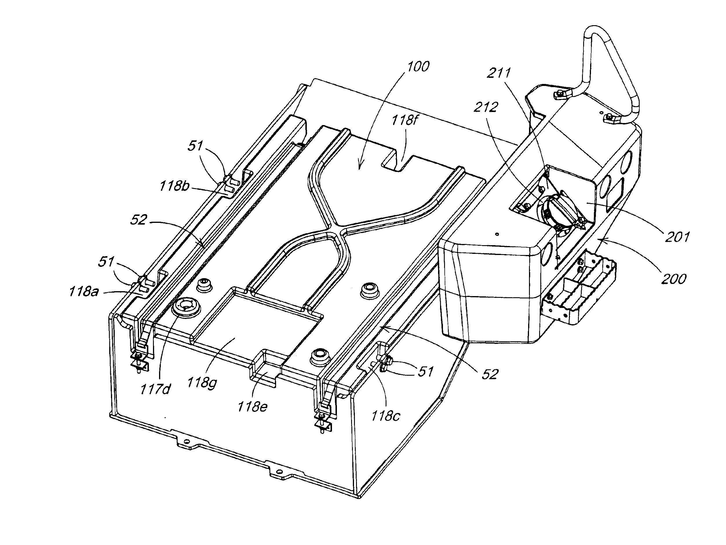
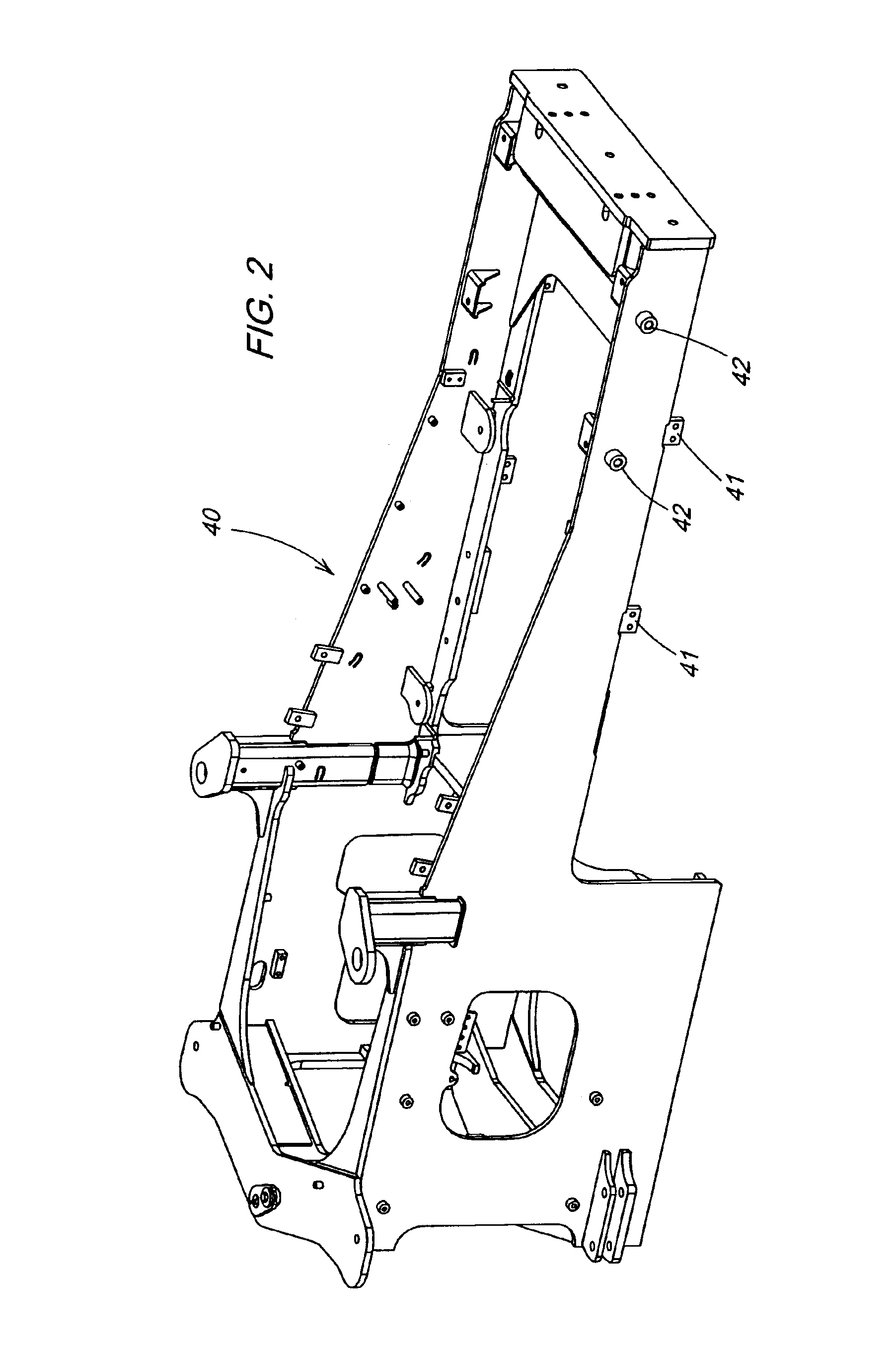
[0017]FIG. 2 illustrates a rear frame 40 for the articulated loader 1 of FIG. 1. Mounted on the rear frame 40 at mounting tabs 41 via screws 51 is a cradle 50 for shielding and positioning an inte...


PUM


Abstract

A fuel system for a work vehicle having fewer points of leakage and a secure or virtually damage proof location for the filler tube of the fuel tank is provided. The fuel system includes an integrated fuel tank which includes a fuel tank and a filler tube integrated as one piece and a counterweight having a complementary portion with a hole of sufficient size to allow passage of the filler tube. The integrated tank and the counterweight are arranged to allow the filler tube to pass through and be surrounded by the complementary portion. The complementary portion may also have a door providing additional protection to the filler tube and a secure and stable stepping area for the operator of the work vehicle.

Description

FIELD OF THE INVENTION[0001]The invention relates to configurations for fuel tanks and fuel tank locations in work vehicles such as, for example, loaders. More specifically, it relates to a structure, system and method of increasing the reliability and convenience of fuel systems in work vehicles by reducing the number of parts in the fuel systems and protecting as well as conveniently locating fuel filler tubes and fuel tanks.BACKGROUND OF THE INVENTION[0002]On many work vehicles such as, for example, loaders, conventional fuel systems include fuel tanks and sundry assortments of associated parts such as filler hoses, filler necks, housings and assorted clamps, o-rings, screws, nuts and bolts for connecting the fuel tank with the associated parts.SUMMARY OF THE INVENTION[0003]The inventors recognize that conventional fuel systems for work vehicles allow fuel tanks to be conveniently and securely located on a work vehicle but significantly increase the risk for leakage with respect ...

Claims


Application Information

Patent Timeline
Patent Type & Authority Patents(United States)
IPC IPC(8): B60K15/04B62D21/18B60K15/03B60K15/063B60K15/067
CPCB60K15/04B60K15/063B60K15/067B62D21/186B60K15/03177B60Y2200/221
Inventor PFOHL, JESSE LEEANGULO, ERIC JUANRUDEN, CHRISTOPHER MICHAEL
Owner DEERE & CO
Why Eureka
Try Eureka