Mirror mounting assembly for controlling vibration of a mirror

a technology for mounting assemblies and mirrors, applied in the field of rear vision mirrors, can solve the problems of high degree of precision required in both directions and the possibility of failure of arrangements

Inactive Publication Date: 2005-09-06
SCHEFENACKER VISION SYST AUSTRALIA
View PDF18 Cites 2 Cited by
  • Summary
  • Abstract
  • Description
  • Claims
  • Application Information

AI Technical Summary

Benefits of technology

[0017]The amount of force used to hold the link will be a balance between maximising the holding force to prevent

Problems solved by technology

However, in order to make both arrangements work, a high degree of precision is required in both moulding and mounting of the componen

Method used


Image

  • Mirror mounting assembly for controlling vibration of a mirror
  • Mirror mounting assembly for controlling vibration of a mirror
  • Mirror mounting assembly for controlling vibration of a mirror

Examples


first embodiment

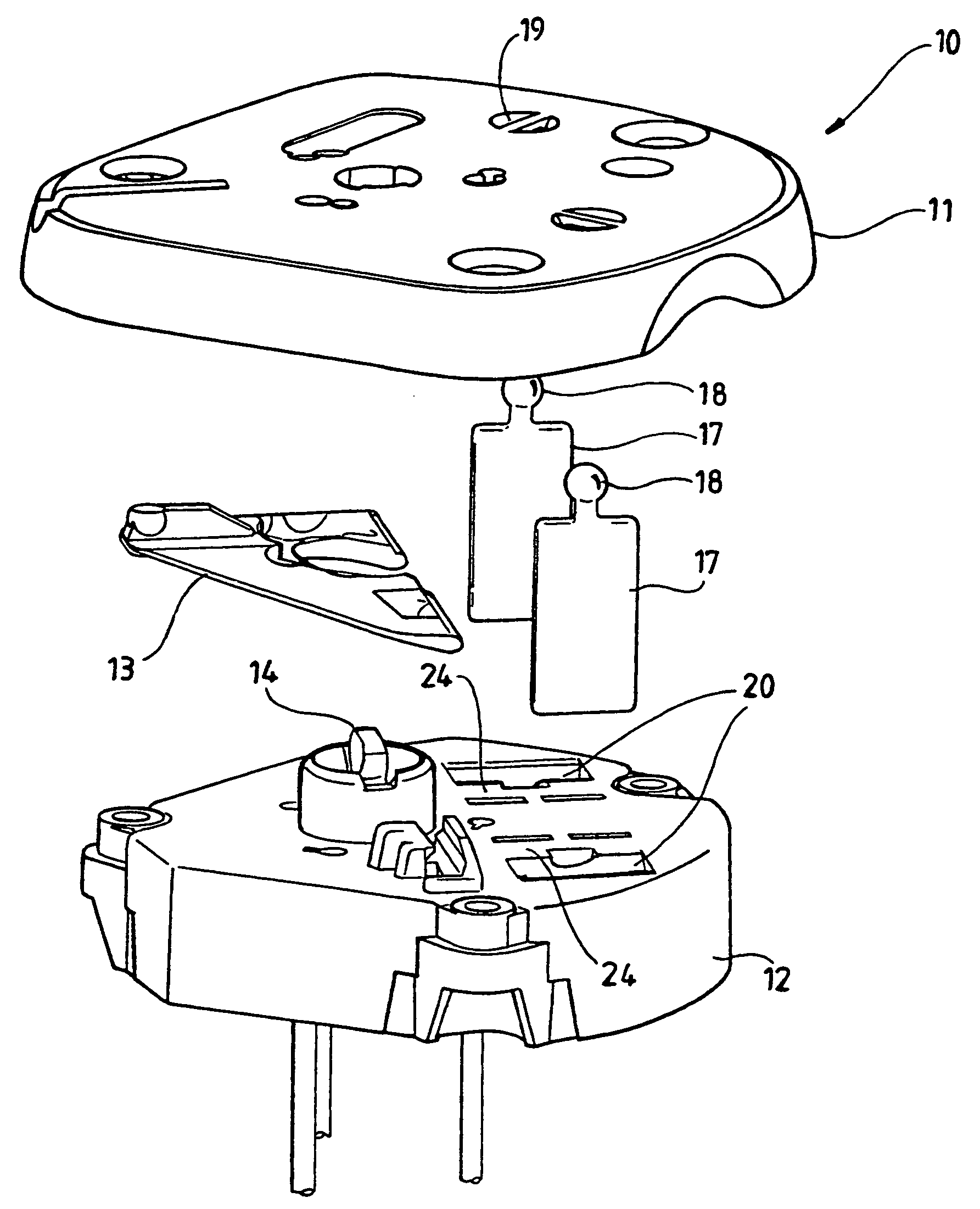
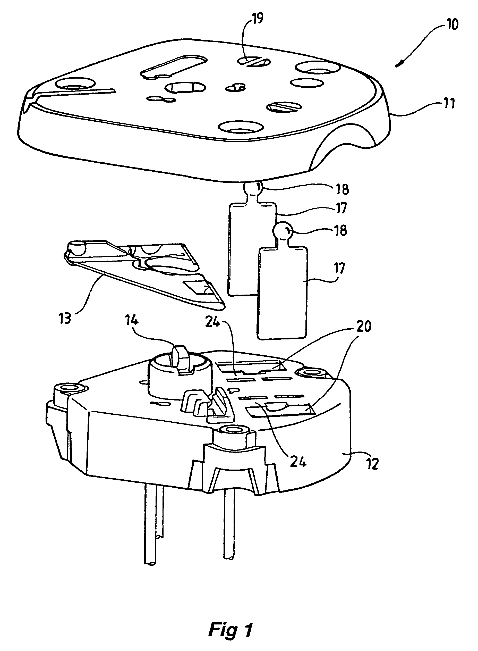
[0025]FIGS. 1 to 3 show the invention. The mirror mounting assembly 10 comprises a mirror support 11 and a base portion 12. The pivoting joint between the mirror support 11 and base portion 12 comprises a yoke 13 and spigot 14. The spigot 14 connects directly to the mirror support 11, and the yoke 13 is pivotally attached to the mirror support 11 and base portion 12 respectively. The yoke 13 prevents rotation of the mirror support 11 with respect to the base portion 12. This connection arrangement allows movement of the mirror support 11 with respect to the base portion 12 about two orthogonal axes.

[0026]The mirror support 11 is designed to have a mirror backing plate attached to it. The mirror backing plate holds the mirror. The base portion 12 is designed to be fixed to mirror body housing such as the shell of a wing mirror. The mirror mounting assembly 10 shown in this embodiment is designed to be manually adjusted.

[0027]In this embodiment, the links that extend between the mirro...

second embodiment

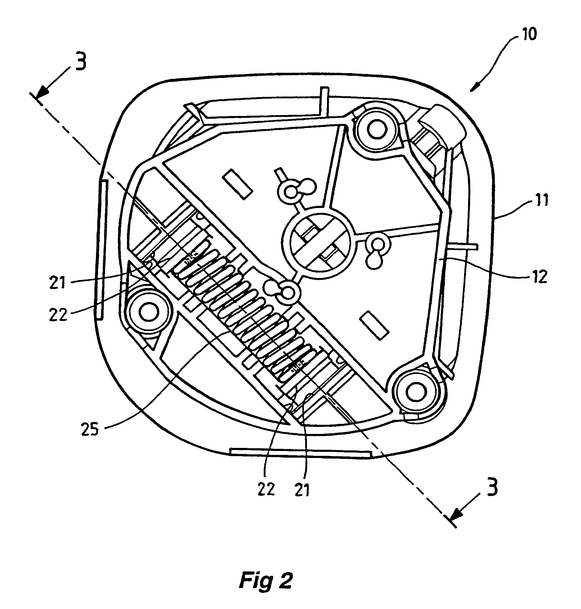
[0033]The compression spring 25 provides a convenient means for adjusting the gripping force applied to the blades 17. The compression spring can be matched to provide the required gripping force which will prevent unwanted movement while at the same time still enabling manual movement of the mirror support 11. FIG. 4 shows the invention. In this embodiment, a single blade 17 and corresponding aperture is used.

[0034]In this embodiment, the aperture is formed by a frame member 28 that has two opposing halves 29 and 30. Held between the opposing halves 29 and 30 are semi-cylindrical gripping pads 31. The blade 17 is inserted between the gripping pads 31.

[0035]The opposing halves 29 and 30 of the frame member 28 are connected by a pair of bands 33. The left side opposing half 29 is shown in dashed outline in FIG. 4. This opposing half 29 is rotated towards the other opposing half 30 and are clipped together. In this embodiment, clip 34 locates over projection 35 so that the opposing ha...


PUM


Abstract

A mirror mounting assembly including a mirror support, a base portion, a pivoting joint between the support and the base portion allowing the support to pivot with respect to the base portion, a link extending between the support and the base portion, a first end of the link being held with respect to either the support or the base portion, an aperture provided in the support or the base portion into which the second end of the link locates, a tight sliding fit between the aperture and the link, the link moving through the aperture allowing the support to be adjusted with respect to the base portion, the fit being such that unwanted movement between the support and base portion is prevented during normal use.

Description

[0001]This invention relates to a mirror mounting assembly, and in particular to a mirror mounting assembly for mounting an adjustable mirror in a manner that will control undesirable vibration or movement of the mirror.BACKGROUND OF INVENTION[0002]It is common for rear vision mirrors, particularly those mounted externally of a vehicle to be adjustable about two orthogonal axes. This adjustment can be by remote, manual or electric means, or by directly adjusting the mirror by hand.[0003]Rear vision mirrors normally comprise a mirror body or shell with a mirror located in the shell. A base is separately mounted within the shell and a mirror support is pivotally attached to the base. This allows movement of the mirror support and the attached mirror about the adjustment axes. The base may also be part of the mirror body or shell moulding.[0004]One principal aim is to minimise unwanted vibration or movement of the mirror support with respect to the base portion. Vibration should be min...

Claims


Application Information

Patent Timeline
IPC IPC(8): B60R1/02B60R1/06F16F15/02
CPCB60R1/02B60R1/06
Inventor MUNYARD, ANDREW GORDON STUARTFINERI, GARRY GORDON LESLIE
Owner SCHEFENACKER VISION SYST AUSTRALIA
Why Eureka
Try Eureka