Magnetic latching solenoid and method of optimization

a solenoid and magneto-locking technology, applied in the direction of electromagnets, valve details, cores/yokes, etc., can solve the problems of loss of mechanical power, reduced cross-sectional area at the entire length of the plunger and stationary pole, and early saturation of the effective surface area. , to achieve the effect of maximizing the attracting for

Active Publication Date: 2010-12-16
BEN ASHER ELDAD +1
View PDF9 Cites 1 Cited by
  • Summary
  • Abstract
  • Description
  • Claims
  • Application Information

AI Technical Summary

Benefits of technology

[0025]maximizing the attracting force by specifying a coil that, during an excitation pulse, restores the value of the flux

Problems solved by technology

However, the flux density B, cannot be increased indefinitely as the core material enters into saturation at a certain flux density level related to the core material.
Reduction of the cross-sectional area at the entire length of the plunger and stationary pole is not recommended since the reluctance of the magnetic circuit increases.
A disadvantage of the suggested conical saturation tip for long stroke solenoids or the flat face for short stroke magnetic latching solen

Method used


Image

  • Magnetic latching solenoid and method of optimization
  • Magnetic latching solenoid and method of optimization
  • Magnetic latching solenoid and method of optimization

Examples


Embodiment Construction

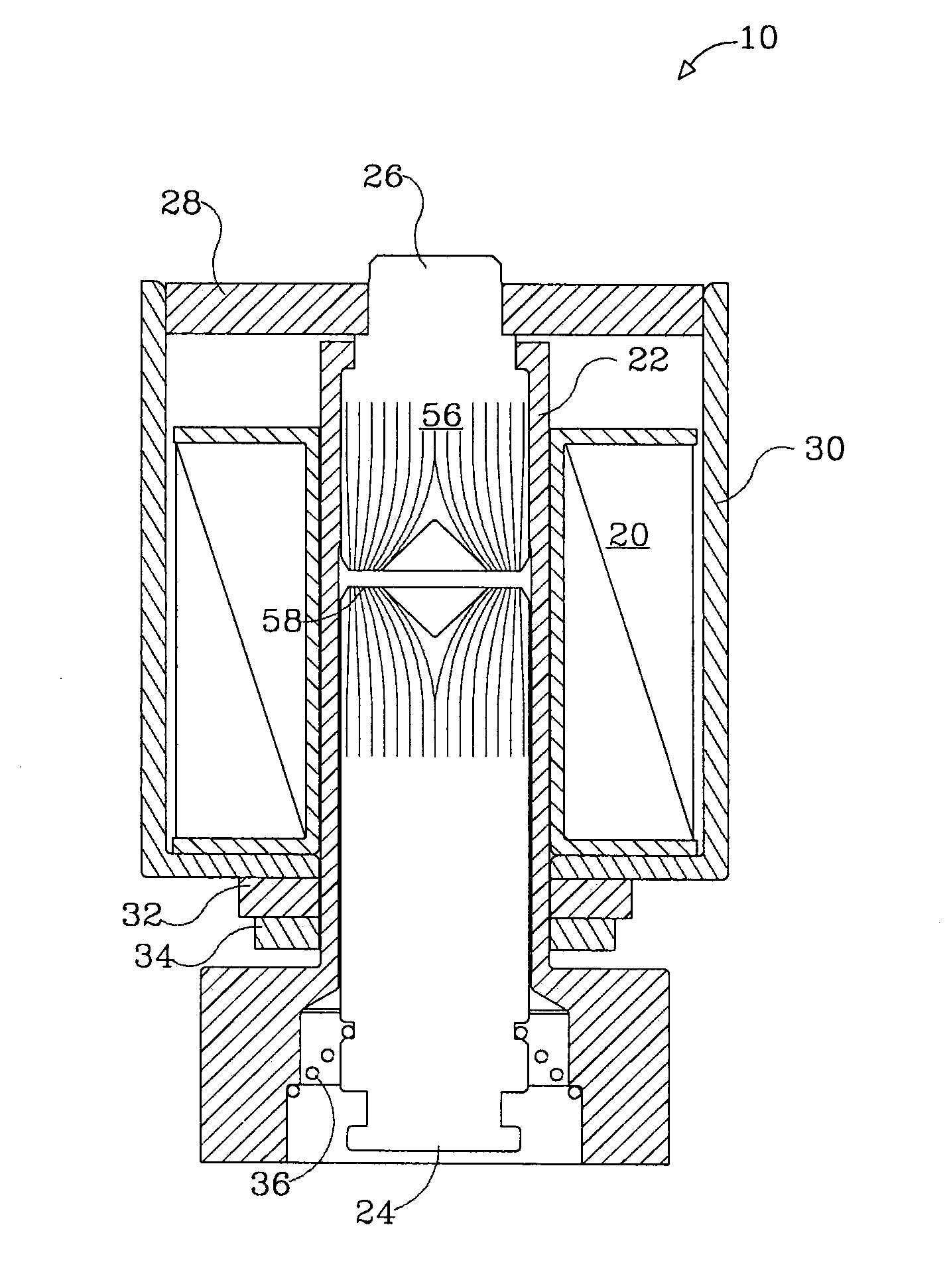
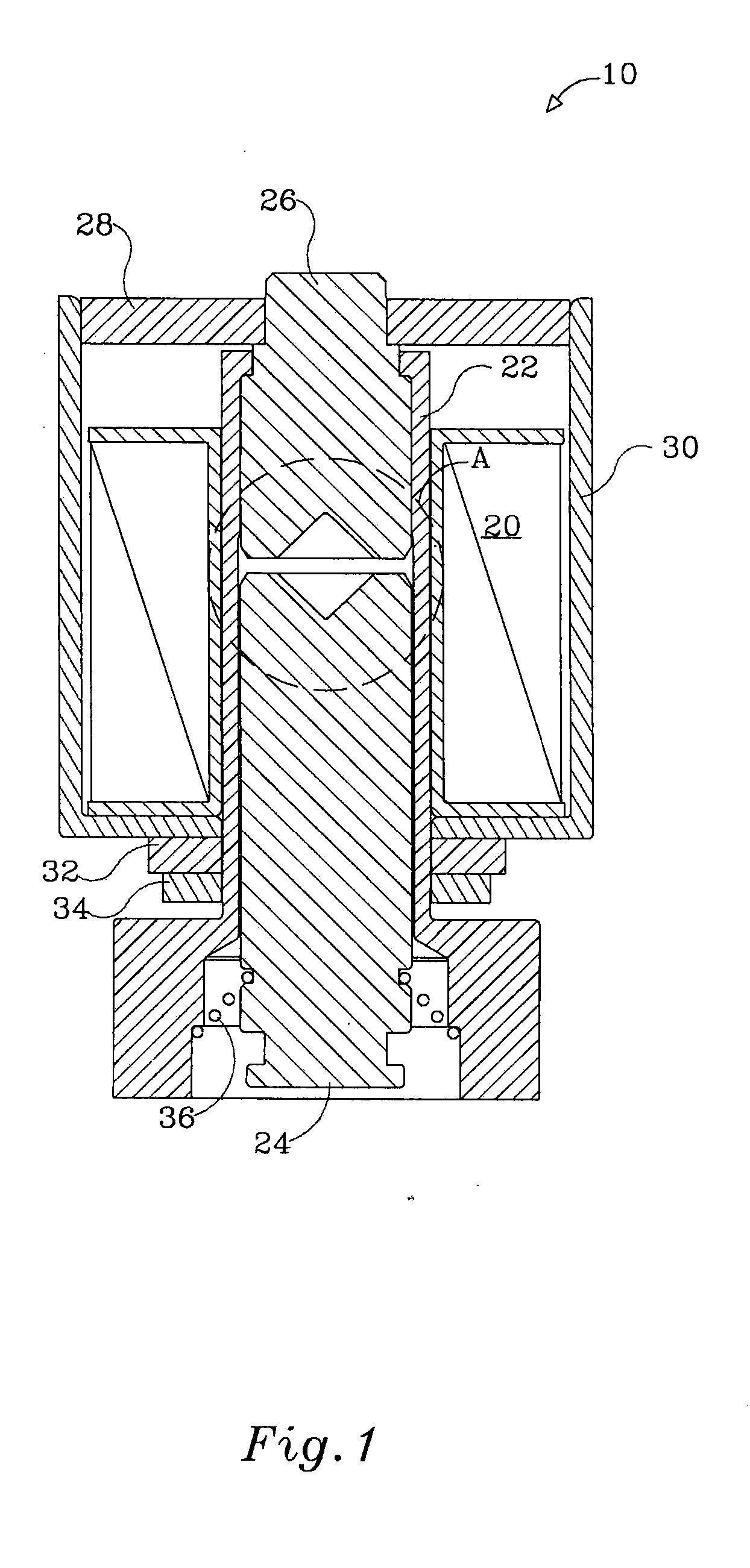
[0030]With reference to FIG. 1, there is shown a magnetic latching solenoid generally referenced 10, comprising a coil assembly 20 wound round a non-ferromagnetic tube 22. A ferromagnetic core in the form of a cylindrical plunger 24 is slideably fitted to linearly translate in the tube 22 upon excitation of the coil assembly 20 by a pulse of electric current. A cylindrical stationary electromagnetic pole 26, positioned in line with the plunger 24, along with flux conductor 28 and frame 30 form together with the plunger 24 a magnetic flux circuit.

[0031]A washer type permanent magnet 32 attached under the frame 30 by a ferm-magnetic retaining ring 34 induces a constant magnetic flux in the magnetic circuit. The size of the permanent magnet 32 is determined such that the magnetic flux in the electromagnetic pole 26 and the plunger 24 is sufficient to induce stress in a spring 36, and obtain the required holding force of the solenoid 10, upon cessation of the pulse of power delivered to...


PUM


Abstract

A magnetic latching solenoid having a coil assembly, a ferromagnetic core slideably fitted to linearly translate upon excitation of the coil assembly by a pulse of electric current, a stationary electromagnetic pole positioned in line with the ferro-magnetic core, at least one flux conductor and a frame, all forming a magnetic flux circuit. A contact area between a face of the ferromagnetic core and a face of the stationary electromagnetic pole is reduced by respective recesses in the ferromagnetic core and the electromagnetic pole, each recess having opposing inclined walls extending from the respective face to a common apex defining a depth of the recess, and forming a residual planar surface of concentrated flux density surrounding the recesses.

Description

FIELD OF THE INVENTION[0001]The present invention relates to magnetic latching solenoids, more particularly, to optimization of the armature contact area in a magnetic latching solenoid.BACKGROUND OF THE INVENTION[0002]A typical electromagnetic solenoid includes a wire coil wound round a stationary electromagnetic pole, and a movable ferromagnetic core (armature) which is separated by an air gap from the stationary electromagnetic pole. A surrounding soft iron frame forms, along with the stationary pole and the movable core, a magnetic circuit which is locally interrupted by the air gap. Upon excitation of the coil by an electric current, a magnetic flux is generated in the magnetic circuit. The magnetic flux results in the movable core being attracted to the stationary pole. The movable core, usually in the form of a plunger, is held in a retracted state until the coil is de-energized, whereupon it is then separated from the stationary pole by gravity if applicable, or by a biasing...

Claims


Application Information

Patent Timeline
IPC IPC(8): H01F7/08
CPCH01F7/1615H01F2007/1669
Inventor BEN-ASHER, ELDADCARO, MICHA
Owner BEN ASHER ELDAD
Why Eureka
Try Eureka