Reprogrammable remote sensor monitoring system

a remote sensor and monitoring system technology, applied in the field of reprogrammable remote sensor monitoring systems, can solve the problems of limited use, unreliable checking, and relative inability to do the job

Inactive Publication Date: 2005-09-06
BRAEMAR MFG
View PDF126 Cites 466 Cited by
  • Summary
  • Abstract
  • Description
  • Claims
  • Application Information

AI Technical Summary

Benefits of technology

[0013]The microprocessor of the sensor interface unit is configured with a unique unit identifier, central monitoring device addressing data, and the initialization data and rules to be employed with each sensor embedded in or interfaced to the unit. The sensor interface unit may be configured on a sensor-by-sensor basis to transmit all sensor data received once activated, or all data meeting certain predefined criteria such as a time window, decibel level, or signal thresh

Problems solved by technology

These systems all employ terminal-antenna packages that are suitcase size and have healthy price tags, and consequently have been limited in use to large trucking firms.
Although these capabilities are valuable, the inventor has recognized that they do not address from a personal perspective a problem of increasing importance in society, which nearly everyone encounters during their lives.
This problem is based upon the need to monitor a remotely located person or other subject that attempts to function normally but may or may be able to do so; and, if the subject does not function normally, notif

Method used


Image

  • Reprogrammable remote sensor monitoring system
  • Reprogrammable remote sensor monitoring system
  • Reprogrammable remote sensor monitoring system

Examples


Embodiment Construction

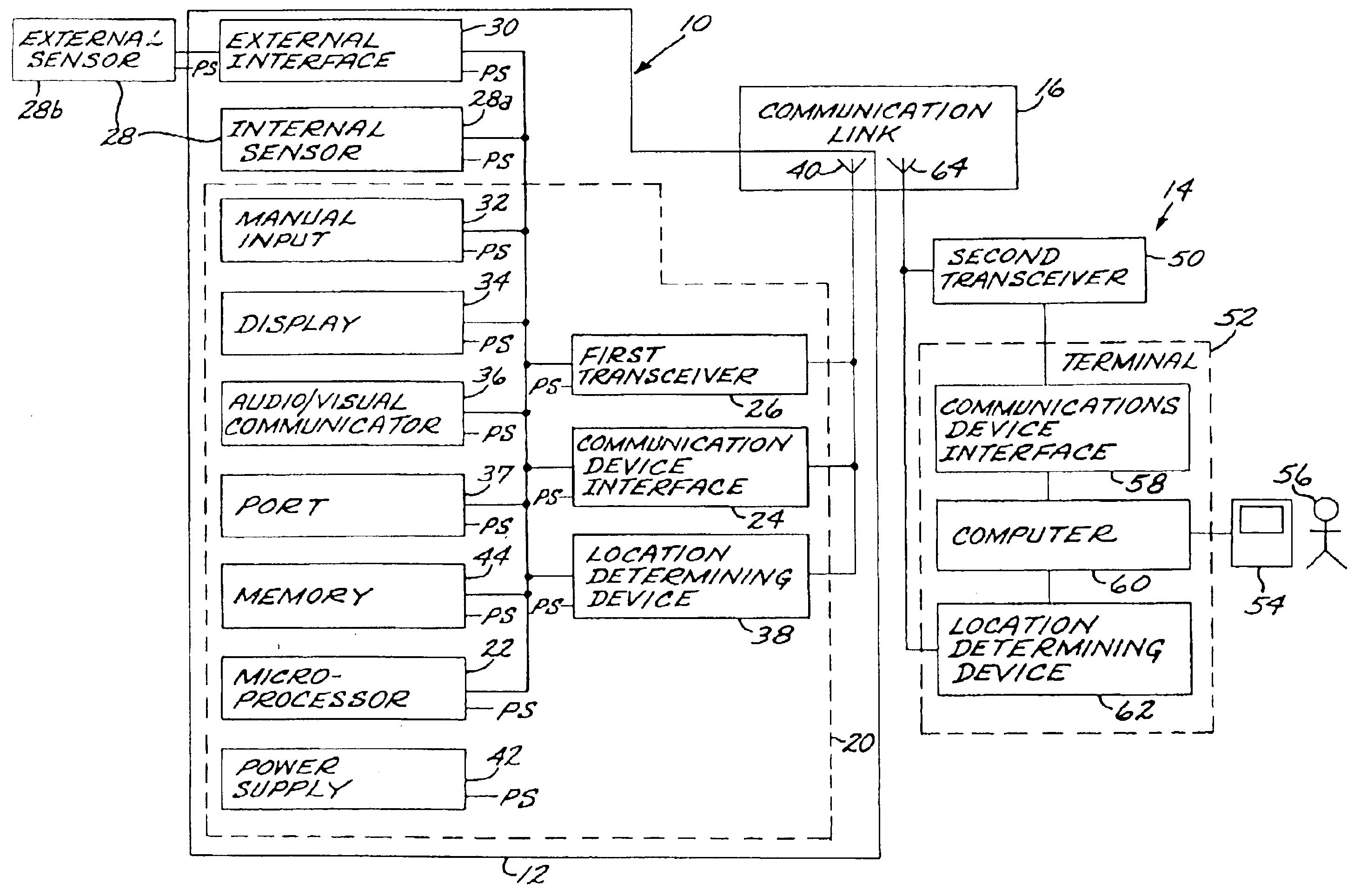
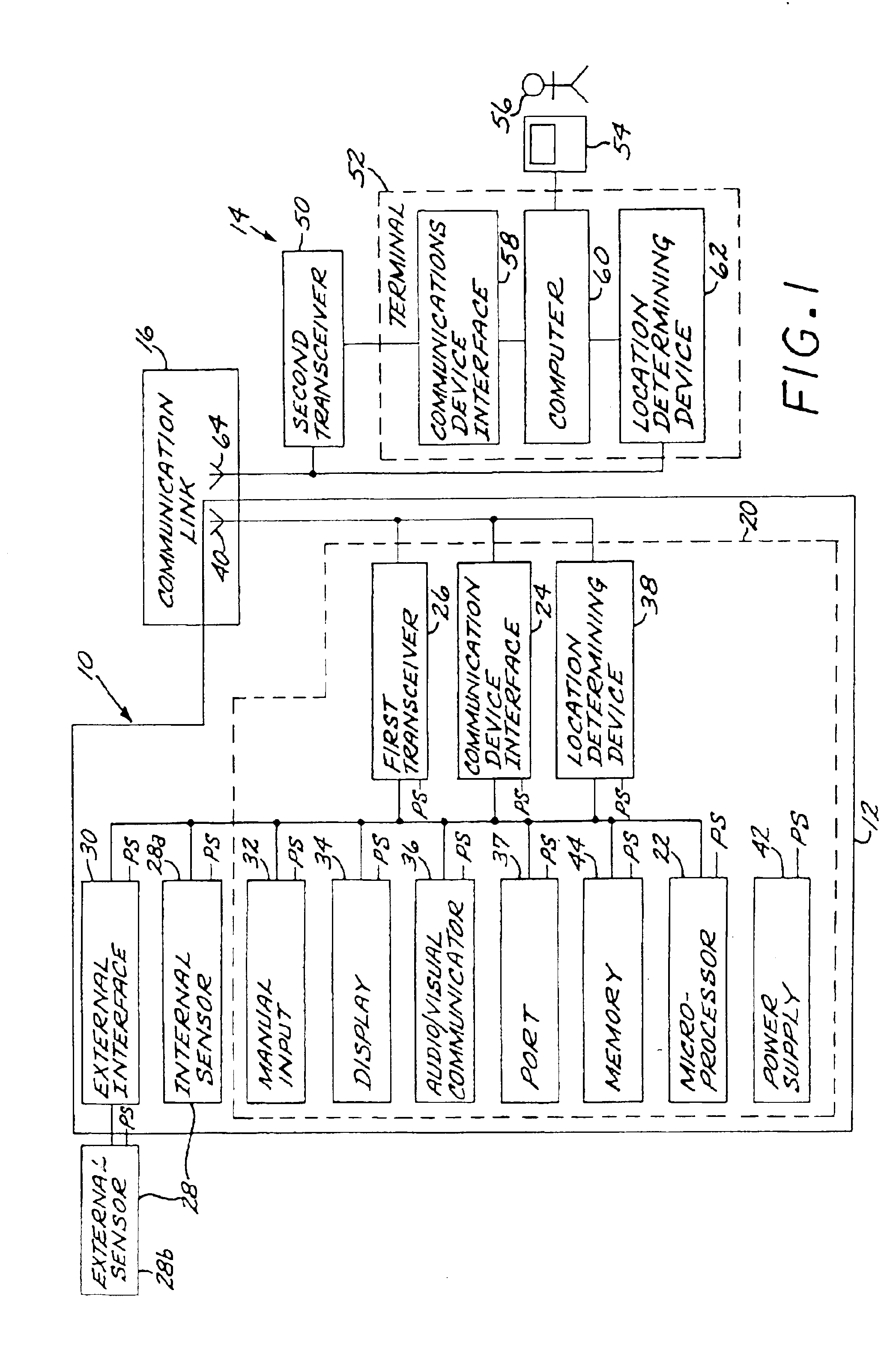
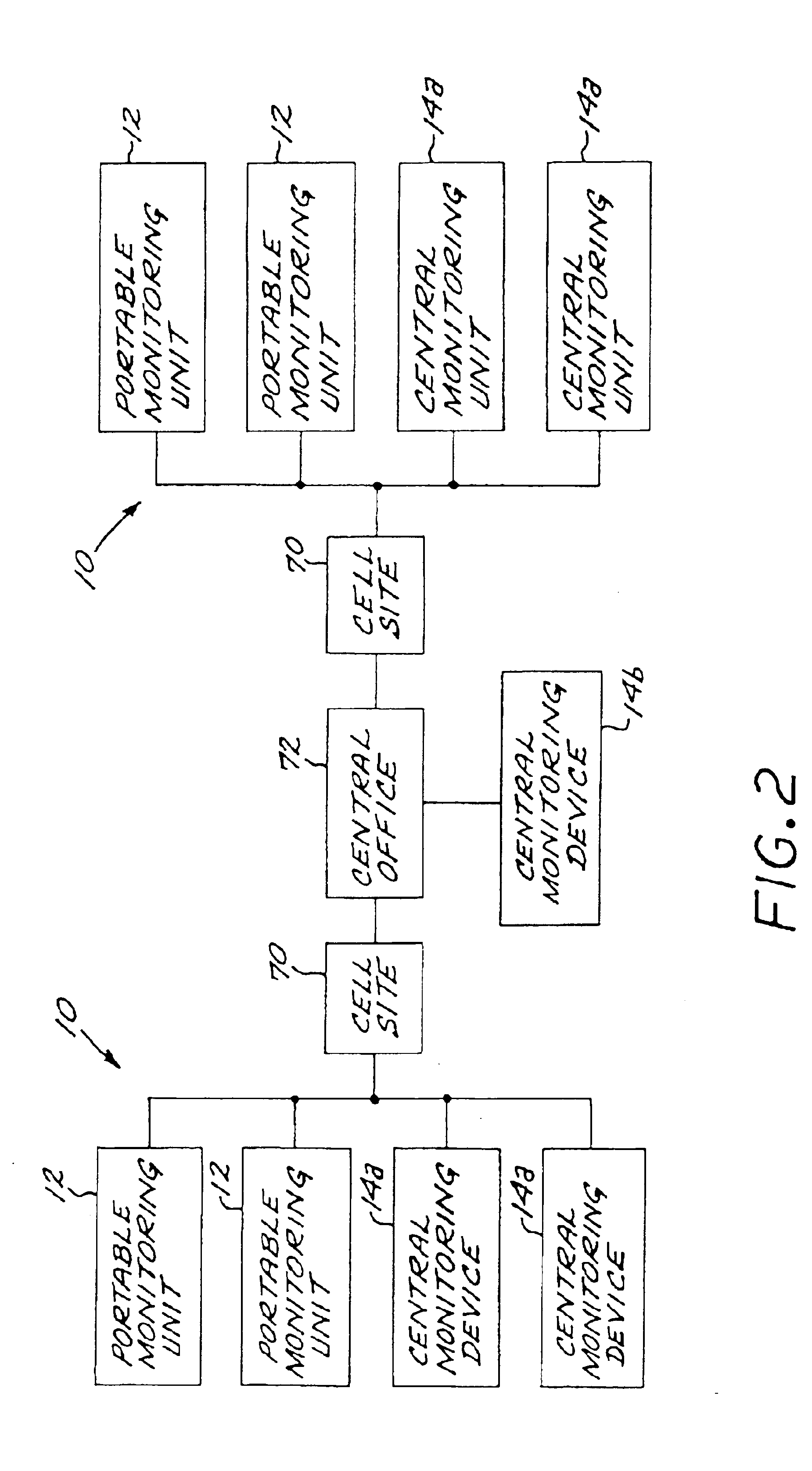
[0022]As shown in FIGS. 1 and 2, an apparatus 10 for remotely monitoring and assessing the status of a subject includes a portable monitoring unit 12 and a central monitoring device 14, which may communicate via a wireless communication link 16. FIG. 1 illustrates a preferred embodiment of the apparatus 10. FIG. 2 illustrates an architecture of the communications link wherein multiple portable monitoring units 12 and central monitoring devices 14 are accommodated.

[0023]The portable monitoring unit 12 includes a sensor interface unit 20 having a microprocessor 22 with multiple inputs and outputs, illustrated in a bus architecture. Communication of the microprocessor 22 with the wireless communication link 16, and thence with the central monitoring device 14, is effected through a communications device interface 24 and a first transceiver 26 of the wireless communication link 16. Information is gathered by one or more sensors 28. It is preferred that the wireless communication link 16...


PUM


Abstract

An automated, real-time, reprogrammable monitoring and control system for portable, remote sensors and subjects includes one or more portable monitoring units, each of the portable monitoring units having a sensor, a location-determining device, and a sensor interface unit. Each sensor interface unit is separately configured to monitor its sensor and to transmit that sensor's data, via a digital wireless communications network, to a central monitoring device. The portable unit is carried or worn by a person or animal, or affixed to an inanimate subject.

Description

[0001]This application is a continuation of application Ser. No. 09 / 829,601, filed on Apr. 9, 2001 which was a continuation of patent application Ser. No. 09 / 357,689, filed Jul. 20, 1999, now U.S. Pat. No. 6,225,901, for which priority is claimed; which in turn is a continuation of application Ser. No. 08 / 813,846, filed Mar. 7, 1997, now U.S. Pat. No. 5,959,529, for which priority is claimed.BACKGROUND OF THE INVENTION[0002]This invention relates to a portable, real-time, reprogrammable sensor monitoring system.[0003]For over fifty years, governments have used both active and passive detection systems to track vehicles and troop movements. Intelligence communities have employed multi-million dollar satellite-based sensors including high-resolution cameras, infrared, and radio direction finding equipment to covertly monitor areas of interest. Only recently have the economies of scale and manufacturing breakthroughs permitted using derivatives of this technology for commercial applica...

Claims


Application Information

Patent Timeline
IPC IPC(8): G08B21/00G08B21/02G01S5/14G08B26/00G01S19/09G01S19/17G01S19/34H04B7/26
CPCG01S19/17G08B13/1963G08B13/19632G08B21/0211G08B21/0216G08B21/0227G08B21/023G08B21/028G08B21/0283G08B21/0294G08B21/245G01S2205/002Y10S706/911Y10S706/924Y10S128/903Y10S128/904G16H50/20G16H40/63G16H40/67
Inventor KAIL, IV, KARL A.
Owner BRAEMAR MFG
Why Eureka
Try Eureka