Method and apparatus for stereoscopic image display

a stereoscopic image and apparatus technology, applied in the field of stereoscopic image display, can solve the problems of reducing resolution and halving the number of display pixels, and achieve the effects of reducing cross talk and moiré, high resolution and high resolution

Inactive Publication Date: 2005-09-06
CANON KK
View PDF7 Cites 74 Cited by
  • Summary
  • Abstract
  • Description
  • Claims
  • Application Information

AI Technical Summary

Benefits of technology

[0008]The present invention has been devised in view of the above and other drawbacks, and it is an object of the present invention to provide a stereoscopic image displaying method and an apparatus using the same, which are capable of displaying a stereoscopic image with high resolution by reducing

Problems solved by technology

This method has a problem such as cross talk that occurs when a direction of display light is disarranged by diffusion of a transmitting type image displaying device such as an LCD or diffraction due to a pixel structure.
In addition, in these co

Method used


Image

  • Method and apparatus for stereoscopic image display
  • Method and apparatus for stereoscopic image display
  • Method and apparatus for stereoscopic image display

Examples


first embodiment

(First Embodiment)

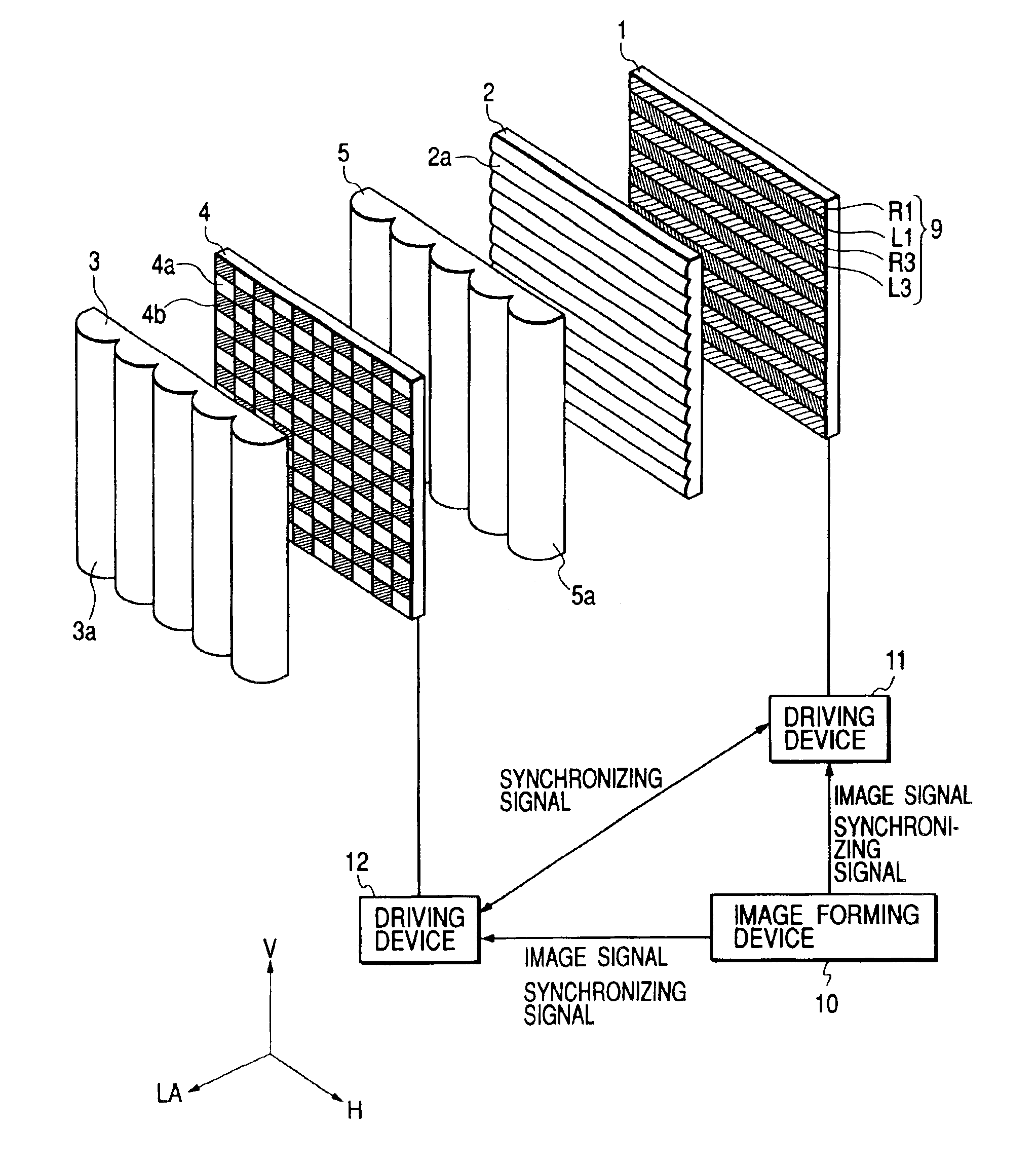
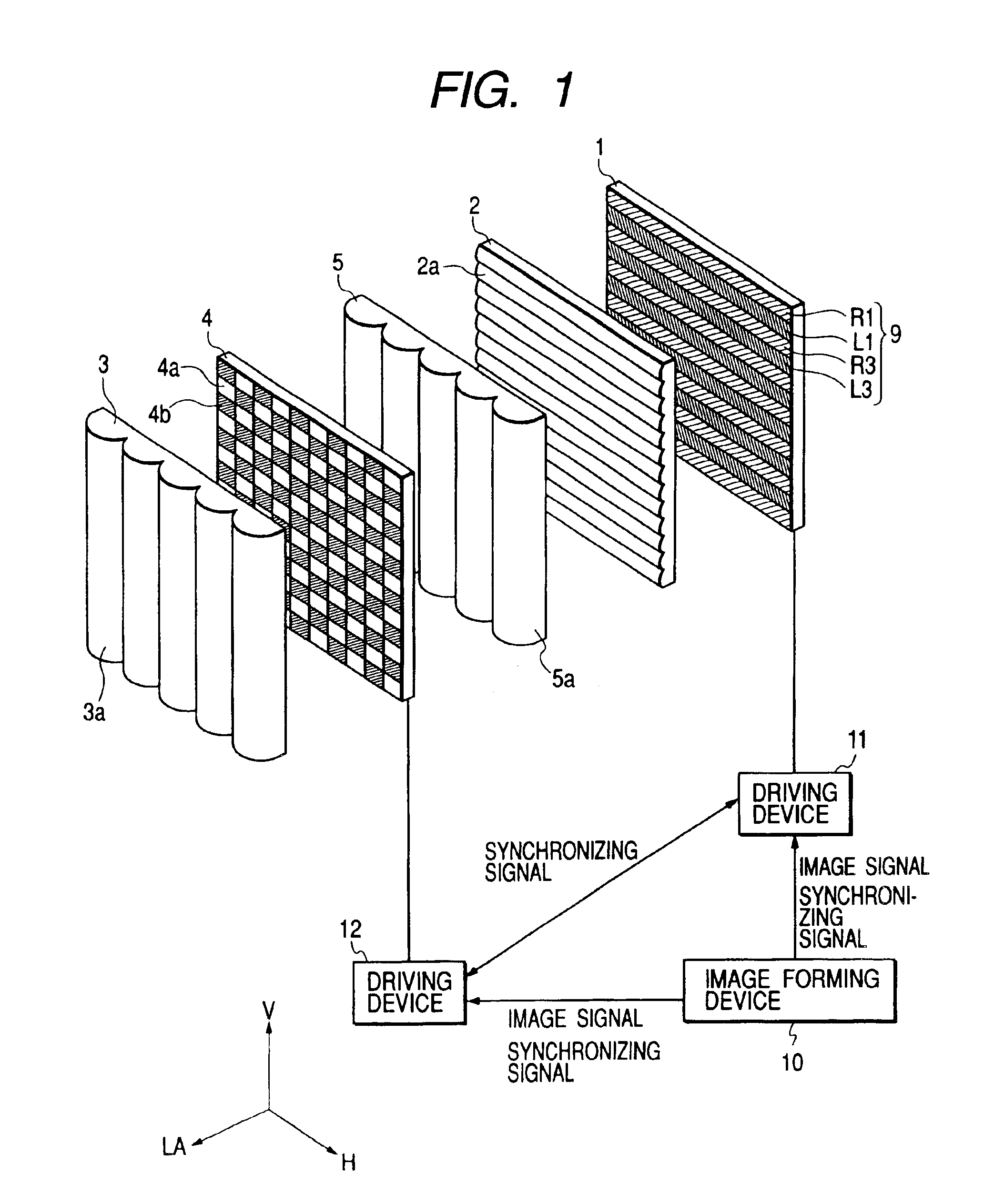
[0062]FIG. 1 is a main part perspective view illustrating an image displaying state at a certain instance in a first embodiment of the present invention. Two pieces (a plurality) of synthesized parallax images that are synthesized from parallax images of two viewpoints (or two or more viewpoints) to be described later are alternately displayed on an image displaying device 1. Reference numeral 2 denotes a horizontal lenticular lens, which has a plurality of cylindrical lenses (optical elements) 2a having a refraction power in the vertical direction V. Reference numeral 3 denotes a first vertical lenticular lens (first optical system), reference numeral 4 denotes an optical modulator that is capable of controlling a light shielding section and a light transmitting section with respect to predetermined polarized light, and reference numeral 5 denotes a vertical lenticular lens (second optical system). The first and the second vertical lenticular lenses 3 and 5 have a...

second embodiment

(Second Embodiment)

[0103]FIG. 12 illustrates a second embodiment of the present invention, in which identical reference numerals are given to the members identical with those in the figures already referred to. This embodiment is different from the first embodiment in that the optical modulator 4 has a first phase shift member 41 that gives transmitted light two different phase shift states by an electric signal and a polarizing optical device 42. Here, this point will be described in detail.

[0104]The image displaying device 1 is configured such that light to be emitted will be linearly polarized light having a polarized face oscillating into a paper surface of the drawing. This can be realized by setting a polarization plate used in an LCD in a predetermined direction if the LCD is used in the image displaying device 1, and can be realized by disposing a polarization plate in the front of a displaying surface of an automatic light emission type displaying device such as a CRT and a...

third embodiment

(Third Embodiment)

[0122]FIG. 20 illustrates a third embodiment of the present invention, in which identical reference numerals are given to the members identical with those of the figures already referred to. This embodiment is different from the second embodiment in that the first phase shift member (π cell) 41 is arranged immediately in front of the image displaying device 1 and, particularly, that it is arranged separately from the polarizer 42 (the second shift member 421 and the polarization plate 422) described with reference to FIGS. 12 to 19.

[0123]In this embodiment, each component is also arranged such that the relations (h1) to (h11) and (v1) to (v3) of the design parameters already described are satisfied. However, the polarizer 42 (or the second phase member 421 and the polarization plate 422) is arranged instead of the optical modulator 4 of the first embodiment, and an interval (optical distance) between each member is determined taking into account an optical thicknes...


PUM


Abstract

It is an object of the present invention to provide a stereoscopic image displaying method and a stereoscopic image displaying apparatus using the same, which are capable of excellently observing a stereoscopic image. In order to achieve the object, a stereoscopic image forming apparatus of the present invention is configured such that display light from an image corresponding to a viewpoint of one parallax image on an image displaying device, on which parallax images corresponding to a plurality of different viewpoints can be displayed, is guided to an optical modulator, on which a light transmitting section and a light shielding section can be formed, by a second optical system disposed in the front of the image displaying device, and that the display light transmitted through the light transmitting section of the optical modulator is collected at a position that is a predetermined distance apart corresponding to the viewpoint on an observation surface by a first optical system, and the entire screen of a parallax image to be displayed on the image displaying device is thereby caused to be incident on each eye by controlling transmitted light from the optical modulator in synchronism with the switching of parallax images to be displayed on the image displaying device when an observer attains stereoscopic viewing of the image information on the image displaying device.

Description

BACKGROUND OF THE INVENTION[0001]1. Field of the Invention[0002]The present invention relates to a method and an apparatus for stereoscopic image display and, in particular, relates to a method and an apparatus for stereoscopic image display with which an observer can observe a stereoscopic image without wearing special spectacles and which are preferred for displaying a stereoscopic image in a television, a video camera, a computer, a game machine or the like.[0003]2. Related Background Art[0004]Conventionally, the parallax barrier method and the lenticular method are known as methods of performing stereoscopic image display on an image displaying device such as a CRT or an LCD. With these methods, a stereoscopic image is displayed by displaying a synthesized stripe parallax image in which parallax images of two or more viewpoints, which are divided in a stripe pattern, are arranged alternately in a predetermined order, and guiding display light from the parallax image only to a vi...

Claims


Application Information

Patent Timeline
IPC IPC(8): G02B27/22H04N13/00G03B35/00G02B30/25G02B30/29G03B35/16H04N13/04
CPCG02B27/2214H04N13/0404H04N13/0409H04N13/0456H04N13/0497H04N13/305H04N13/31H04N13/361H04N13/398G02B30/29G02B30/27
Inventor TANIGUCHI, NAOSATOINOGUCHI, KAZUTAKANISHIHARA, HIROSHITAKIKAWA, TOMOSHISAITO, YOSHIHIROMORISHIMA, HIDEKI
Owner CANON KK
Why Eureka
Try Eureka