Hinge device with detent

a technology of hinges and detents, which is applied in the field of hinges, can solve the problems of increasing installation time and production costs, prone to unauthorized access to enclosures, and complex hinges, and achieves the effect of convenient installation

Inactive Publication Date: 2005-09-13
SOUTHCO
View PDF28 Cites 18 Cited by
  • Summary
  • Abstract
  • Description
  • Claims
  • Application Information

AI Technical Summary

Benefits of technology

[0012]An object of the present invention is to provide a wing or leaf-type hinge assembly that can be readily installed on a thin panel or lid.
[0013]Another object is to provide this hinge assembly with a backing plate for increased durability and for covering attachment parts.
[0015]An even further object is to provide this hinge assembly with a detent mechanism that assists in holding the hinge assembly in a pre-selected position.

Problems solved by technology

The addition of the adjustment elements, while facilitating the positioning of a hinge, also increases the installation time and the production cost.
This type of hinge, however, has the problem of being susceptible to permitting unauthorized access to an enclosure by removing the hinge pintle.
Although some solutions have been provided by furnishing additional hinge components, such as the “hinge pintle retaining means”, shown by Curry, et al. in U.S. Pat. No. 4,073,037, the added components make the hinge more complex, and can increase installation and production costs.
Such leaf hinges, as shown by Curry et al. do not solve the fundamental problem of the hinge coming loose or the hinge bending the thin panel or lid to which it is attached.

Method used


Image

  • Hinge device with detent
  • Hinge device with detent
  • Hinge device with detent

Examples


Embodiment Construction

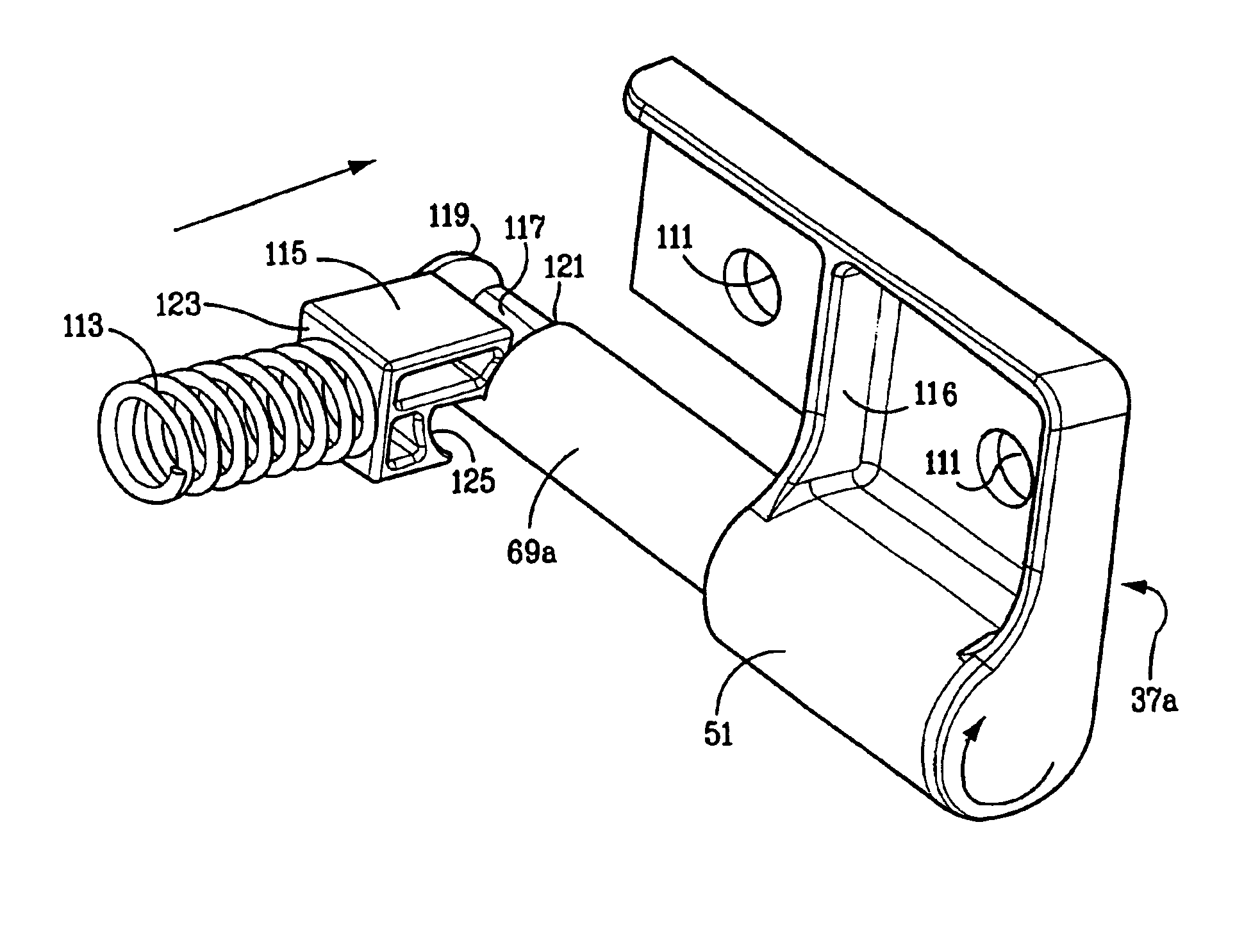
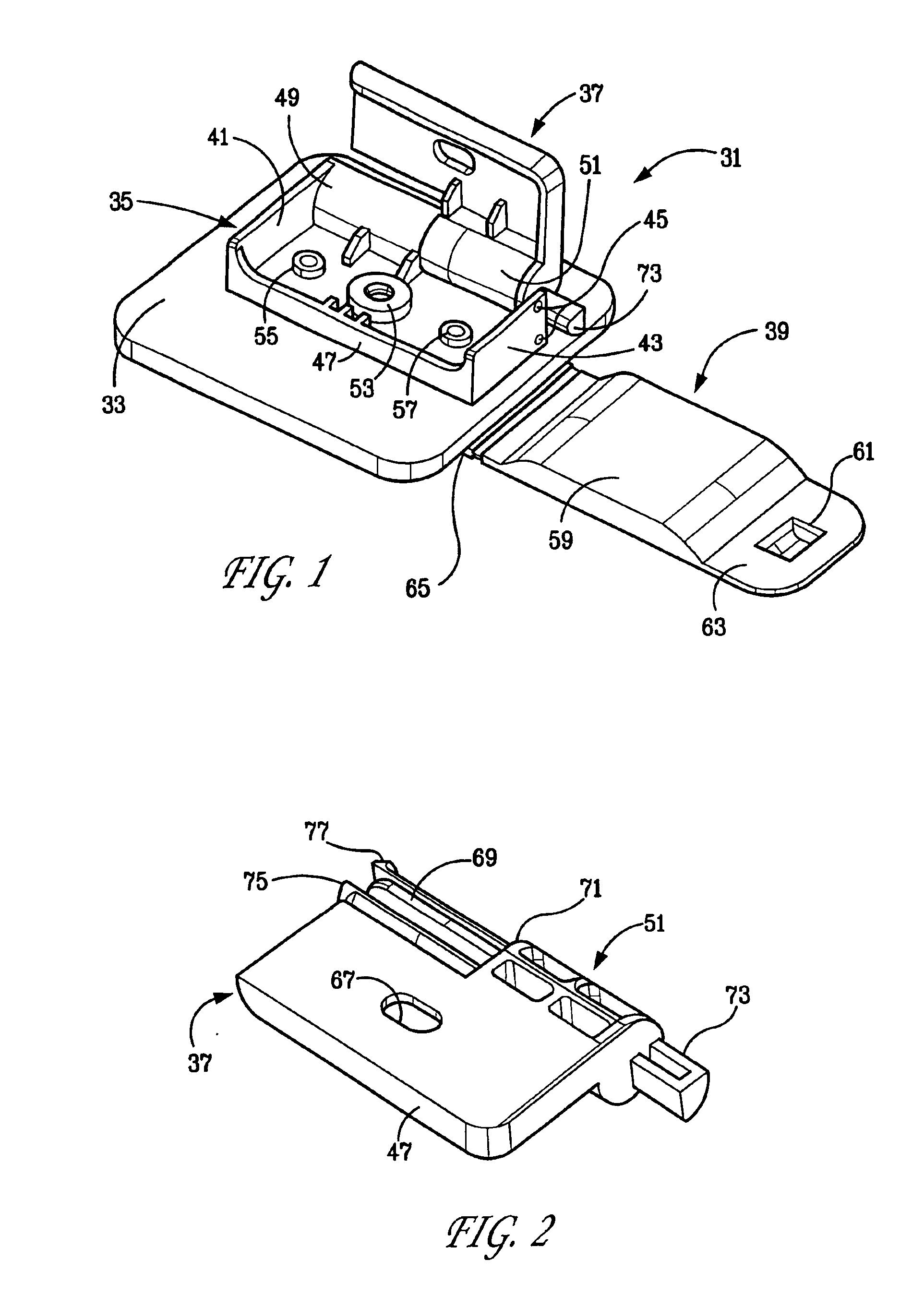
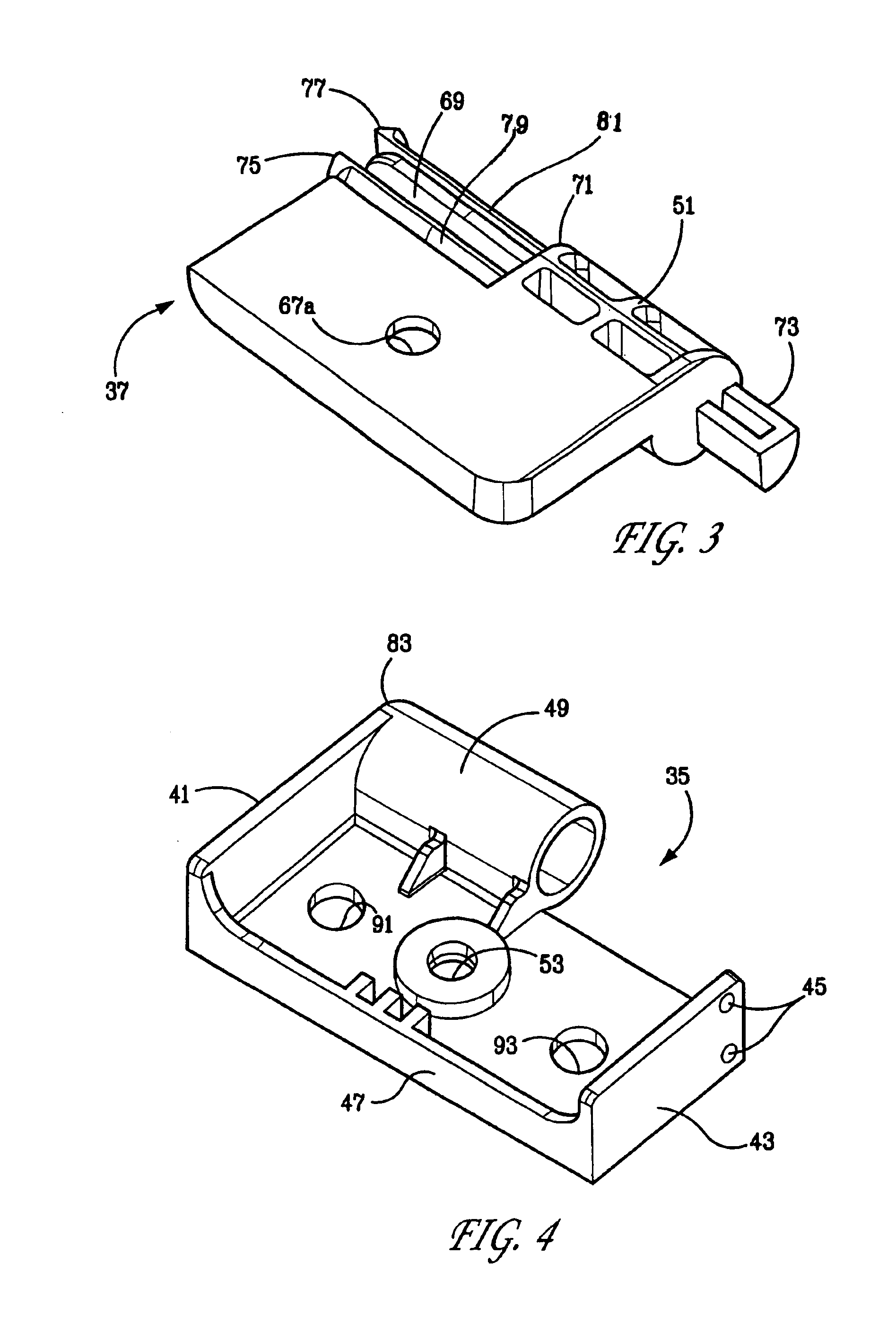
[0049]The present invention is a hinge assembly having leaf or wing-type plate members, this hinge assembly being suitable for mounting to a thin panel or lid and having a snap-together configuration. The hinge assembly includes a male wing plate member and a female wing plate member joined with a pivot pin for rotation with respect to one another. A backer plate forms a support member for the female wing member, which is mounted to the thin panel itself.

[0050]The backer member can carry one or more fastener openings in its face, which abuts the thin panel. This backer member can alternately carry one or more fasteners projecting from its face. A backer member configuration having the fastener openings can also include a cover. Positioning pins or dowels may be present on the face of the backer member for extending through the thin panel and through the face of the female wing member. Such positioning pins can eliminate the need for plural female wing member fasteners.

[0051]The male...


PUM


Abstract

A wing or leaf-type hinge assembly for use with a thin panel or lid installation includes a manual snap assembly of its pivot pin. The pivot pin structure includes an interlock, which requires a positive release for disassembly. A backer support plate permits the sandwiching of the thin panel between one wing or leaf member of the hinge and the support plate. A detent mechanism may be included which assists in maintaining (holding) the hinge assembly in a pre-selected position. A sensor may be added to detect the hinge assembly in the open position. Mounting structures assist in the easy mounting of the hinge with fewer fasteners.

Description

[0001]The present application claims priority of U.S. Provisional Application No. 60 / 348,659, filed Jan. 14, 2002, for Hinge Device with Detent Feature.BACKGROUND OF THE INVENTION[0002]The present invention relates to hinges for supporting thin doors, panels, lids, and thin covers and the like.[0003]Various types of hinge assemblies are known in the art and are particularly useful for securing a door, cover or the like to a frame or other hinging surface. In many cases, hinge assemblies include multiple parts that must be connected and assembled for installation. There are leaf hinges which can comprise a single piece hinge member, which itself, may consist of a group of elements. A leaf hinge typically has one “wing” plate mounted to a door panel and another wing plate mounted to a frame, thereby facilitating the door panel to swing relative to the frame. There are also adjustably provided hinges that contain elements that can be adjusted to position the hinge. The addition of the ...

Claims


Application Information

Patent Timeline
Patent Type & Authority Patents(United States)
IPC IPC(8): E05D5/12E05D7/10E05D7/12E05D11/00E05D11/06E05D11/10
CPCE05D5/04E05D5/125E05D7/1077E05D7/12E05D11/00E05D11/06E05D11/1064E05Y2400/324E05Y2400/326
Inventor PINTO, ANA CHRISTINA
Owner SOUTHCO
Why Eureka
Try Eureka