Method for determining effective coefficient of thermal expansion

a technology of effective coefficient and thermal expansion coefficient, which is applied in the direction of material heat development, program control, instruments, etc., can solve the problems of significant dimensional machining errors, inaccuracy of calculations, and non-uniform expansion of the machin

Inactive Publication Date: 2005-09-13
FIVES MACHINING SYST +1
View PDF20 Cites 23 Cited by
  • Summary
  • Abstract
  • Description
  • Claims
  • Application Information

AI Technical Summary

Benefits of technology

[0016]The present invention is for a method for determining an “effective” thermal coefficient of a machine comprised of members and for a method for using such effective thermal coefficient to calibrate the machine and of the members thereof for thermal expansion thereof. The method for determining an “effective” thermal coefficient of a machine according to the preferred embodiment hereof comprises the steps of installing one or more temperature sensors, such as conventional thermocouples, at various locations on the machine, positioning a first machine member at a known “reference” location, relative to a second machine member, installing a linear position measuring device to detect changes in position of the first machine member relative to the second machine member along a first axis of movement, periodically acquiring readings from each of the temperature sensors and from the linear position measuring device during a test cycle and compili...

Problems solved by technology

However, the “true” value of the thermal coefficient may be different from the “textbook” value thereof and thermal expansion measurements and calculations of machine members based on a “textbook” value of the thermal coefficient α may lead to inaccurate calculations, albeit generally of small magnitudes.
Nevertheless, in machining operations, such as those typically performed by profiler machines, where high degrees of machining accuracy are required, even minimally inaccurate calculations may lead to significant dimensional machining errors.
It would not be uncommon for the parts to be constructed from different materials, in which case each material typically will have a unique thermal coefficient α, and the parts of the machine will expand at different rates leading a non-uniform expansion of the machine.
The rails are fixedly anchored to the machine shop floor by several structural bolts, thereby limiting the free thermal elongation of the rails.
However, because the rails are constrained, conventional thermal expansion calculations based upon “textbook” values of the thermal coefficient α likely will not accurately predict the expansion of the rails due to increases in the temperature thereof.
That is, the temperature of the machine varies (sometimes widely) across the entire machine, making it difficult to determine where to measure the temperature of the machin...

Method used


Image

  • Method for determining effective coefficient of thermal expansion
  • Method for determining effective coefficient of thermal expansion
  • Method for determining effective coefficient of thermal expansion

Examples


Embodiment Construction

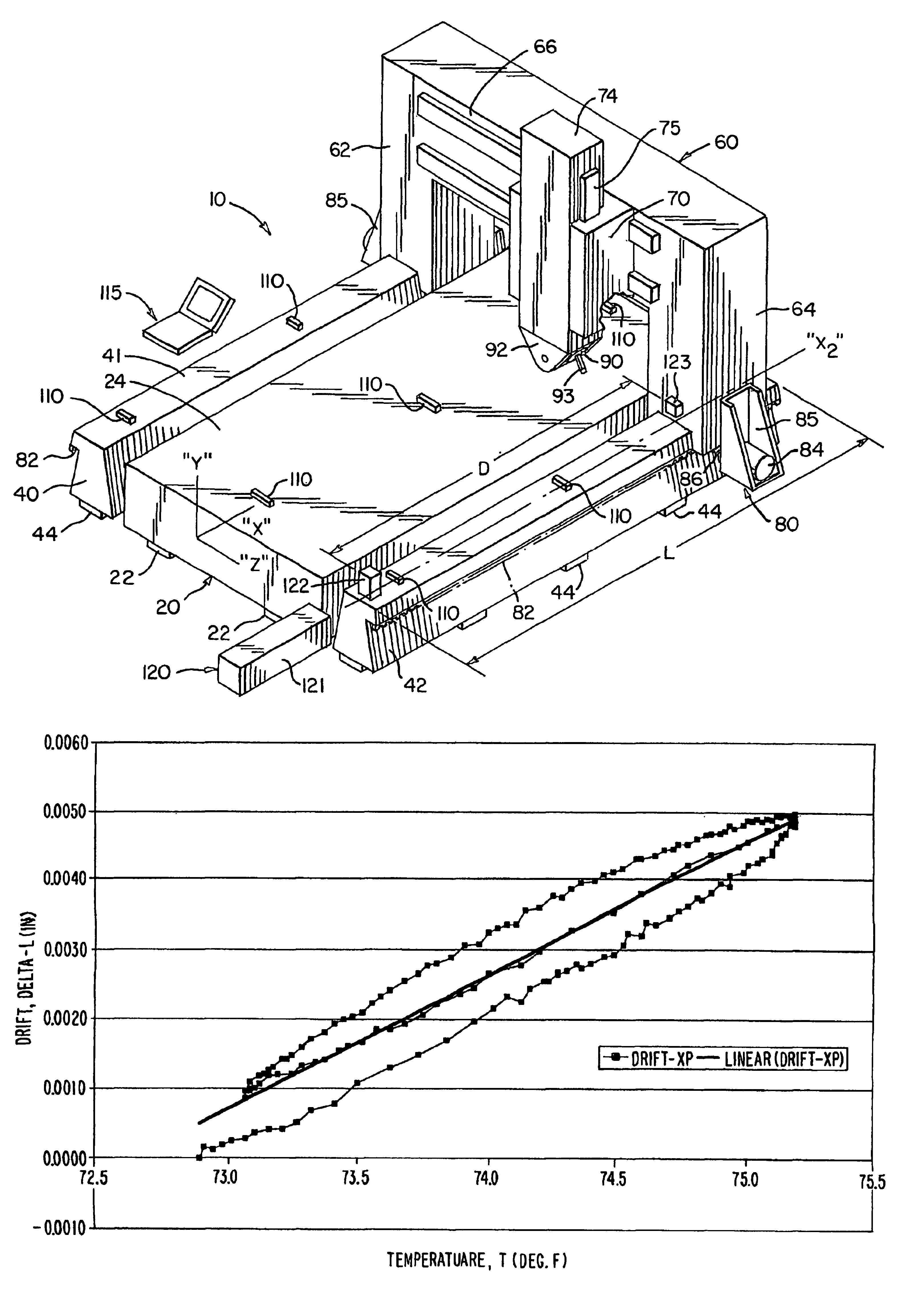
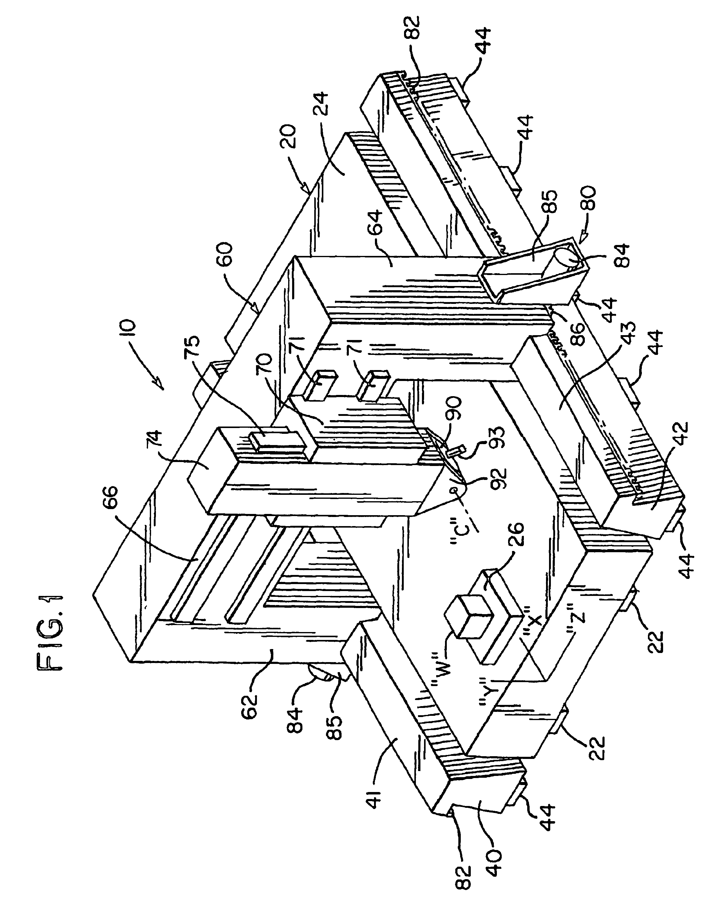
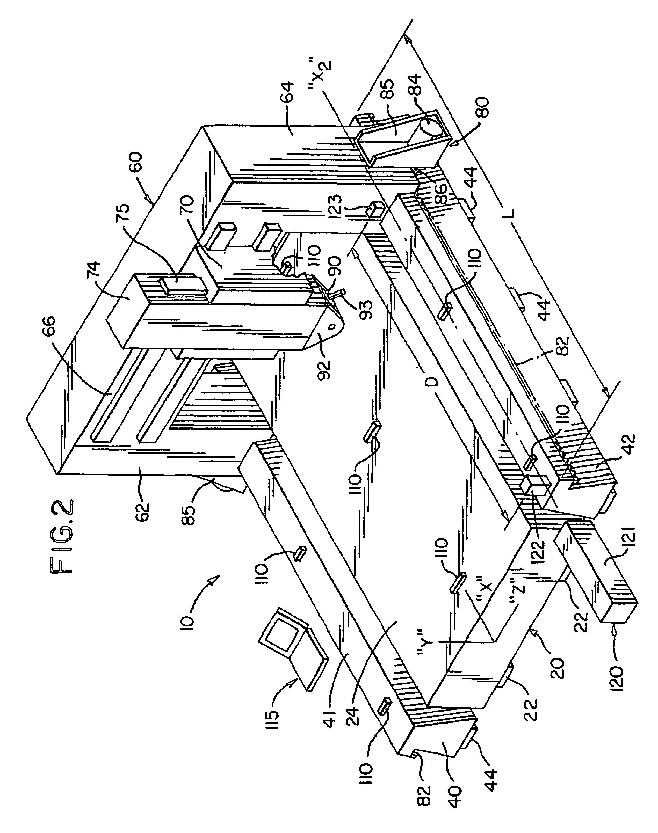
[0034]with reference to FIG. 1, a gantry-style machine tool 10 (sometimes referred-to herein as a “profiler” machine) includes an elongate bed 20 resting on pads 22 and being anchored to the machine shop floor, such as, by structural bolts (not shown), connecting the bed 20 to the floor through the pads 22. A lengthwise direction of the bed 20 defines an “X” axis thereof. The bed 20 preferably is constructed from a single piece of structural steel (as shown) having a substantially continuous planar work surface 24 which is machined to have a flat, uniform finish. Alternatively, the bed 20 may be constructed from a plurality of sections (not shown), in which case the sections are connected to one another to form the work surface 24.

[0035]A workpiece-holding device 26 is securely affixable to the work surface 24 at any number of a plurality of locations thereon and is adapted to securely hold a workpiece “W” thereto. Alternatively, the workpiece “W” may be securely affixed to the work...


PUM


Abstract

A method for determining an “effective” thermal coefficient of a machine comprises the steps of installing one or more temperature sensors (110) at various locations on the machine, positioning a first machine member (60) at a “known” reference location, relative to a second machine member (42), installing a linear position measuring device (120) to detect changes in position of the first machine member (60) relative to the second machine member (42) along a first axis of movement, periodically acquiring readings from each of the temperature sensors (110) and from the linear position measuring device (120) during a test cycle and compiling the temperature and linear position data into a table. A statistical correlation analysis is performed to determine which of the temperature sensors (110) experiencing changes in temperature are most linearly related to changes in the linear position of the first machine member (60) relative to the second machine member (42) and an “effective” coefficient of thermal expansion is thereafter determined as the rate of change of position, i.e. length, relative to change in temperature. The present method includes using the machine's “effective” thermal coefficient the calibrate the motion of the machine to compensate for the thermal characteristics thereof.

Description

[0001]This application claims the benefit of Provisional Application No. 60 / 215,473, filed Jan 30, 2000.BACKGROUND OF THE INVENTION[0002]The present invention relates to methods for determining linear positioning inaccuracies of a moving member of a machine due to thermal expansion of the machine member and of the machine. More particularly, the present invention relates to a method for determining linear positioning inaccuracies of a moving member of a machine due to thermal expansion of the machine member and of the machine, wherein an effective coefficient of thermal expansion of the machine is derived empirically, and wherein such effective coefficient of thermal expansion is used to compensate for such positioning inaccuracies.[0003]Large metal-working machines, such as, for example, gantry-style machine tools (oftentimes referred-to by those skilled in the art as “profiler machines”), are constructed largely out of structural steel. Like other materials used to construct machi...

Claims


Application Information

Patent Timeline
IPC IPC(8): G01N25/16G01N25/00G01B5/00
CPCG01B5/0014G01N25/16G05B2219/49206G05B2219/49207G05B2219/49212G05B2219/49218
Inventor SHIVASWAMY, SATISHCURLESS, RICHARD
Owner FIVES MACHINING SYST
Why Eureka
Try Eureka