
Wheel bearing device

a technology of bearing device and wheel bearing, which is applied in the direction of bearing unit rigid support, mechanical equipment, transportation and packaging, etc., can solve the problems of difficult use of wheel bearing device in automobiles, and achieve the effect of improving the durability of the devi

Inactive Publication Date: 2005-09-13
NTN CORP
View PDF3 Cites 2 Cited by
  • Summary
  • Abstract
  • Description
  • Claims
  • Application Information

AI Technical Summary

Benefits of technology

[0018]The irregular portion hardened by heat treatment is provided at the fitting member, and the plastic deformation portion of the member, which is located inside, that has been plastically deformed is firmly engaged with the irregular portion. In this way, the joining strength between the wheel hub and the fitting member can be increased and the durability of the wheel bearing device can be increased. In this case, when the plastic deformation portion is not subjected to heat treatment, the plastic deformation portion can readily be plastically deformed and surely engaged with the irregular portion.
[0032]The load carrying capacity of a bearing including a rolling element on an inboard side out of the double-row rolling elements may be higher than that on an outboard side. In this way, the useful life of the two bearings can be balanced, so that the durability of the device can substantially be improved.

Problems solved by technology

Therefore, the joining strength between the wheel hub and the fitting member is not sufficient, which makes it difficult to use the wheel bearing device in an automobile.

Method used


Image

  • Wheel bearing device
  • Wheel bearing device
  • Wheel bearing device

Examples


Embodiment Construction

[0054]Now, embodiments of the present invention will be described with reference to FIGS. 1 to 16.

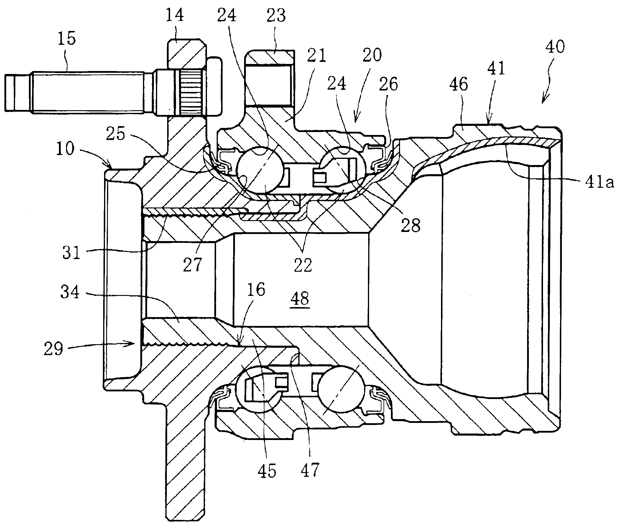
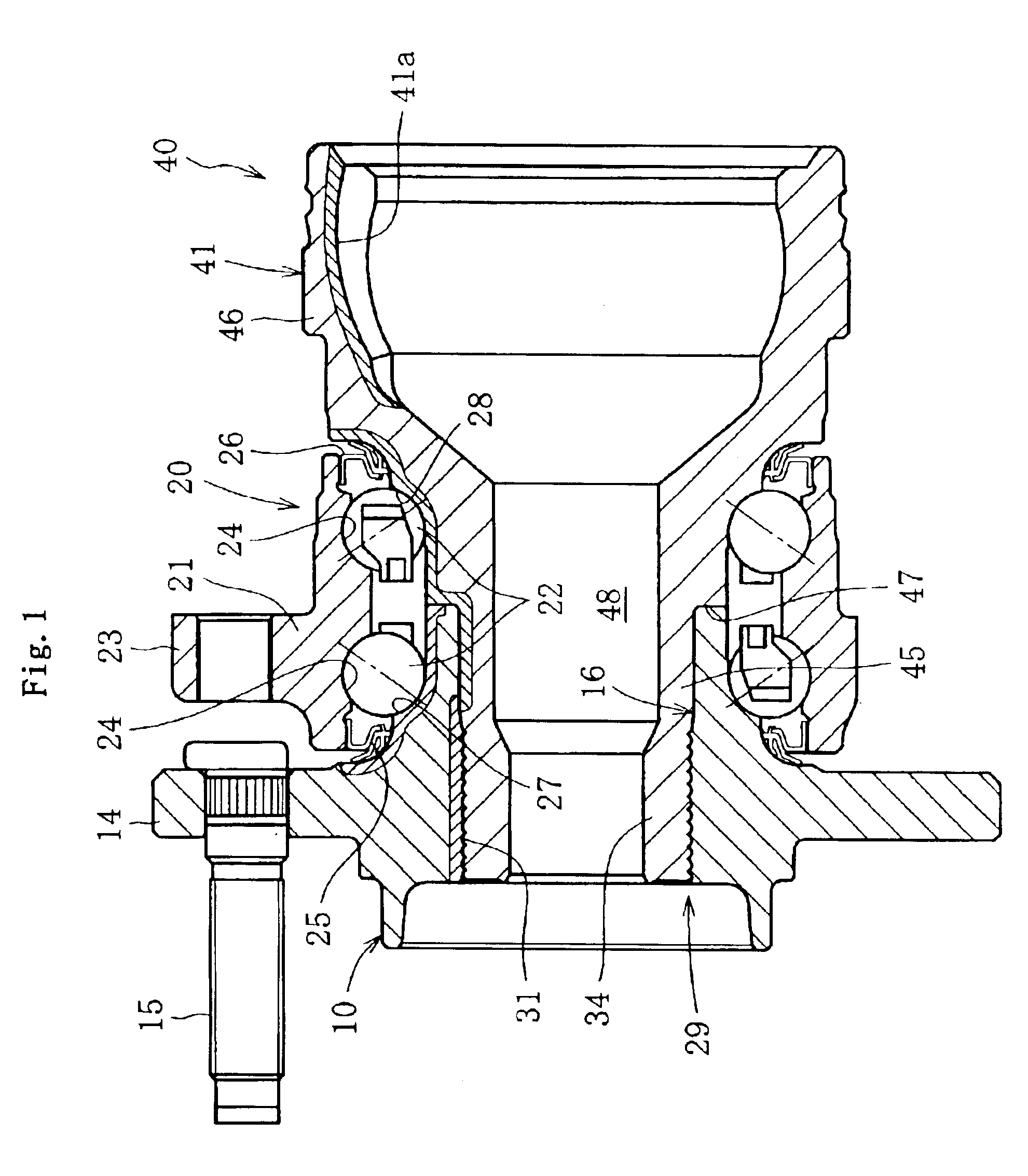
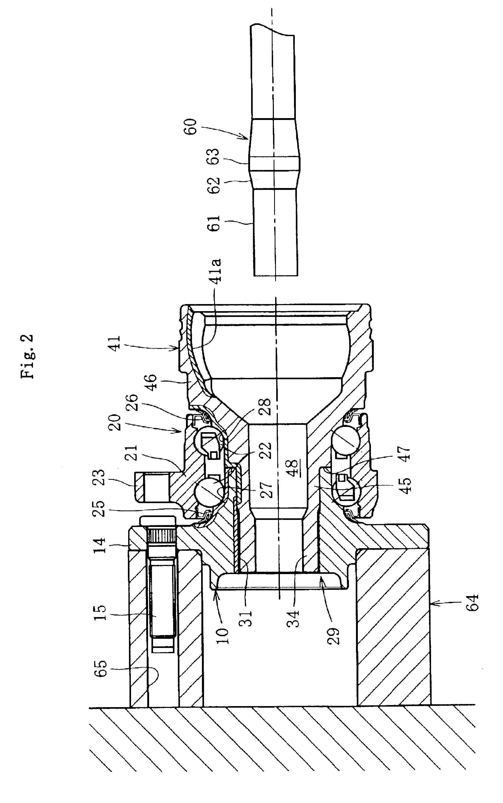
[0055]FIG. 1 shows a wheel bearing device for drive wheels to which the invention is applied. The wheel bearing device includes a wheel hub 10, a bearing 20, and a constant velocity joint 40, and these elements are formed as a unit. Note that the side of the bearing device located on the outer side of the vehicle as it is mounted on the vehicle is referred to as “outboard side” (the left in each of the drawings), while the side of the bearing device near the center of the vehicle is referred to as “inboard side” (the right in each of the drawings).

[0056]The wheel hub 10 having an axial bore in the axial center is hollow inside. A wheel attachment flange 14 for attaching a wheel (not shown) is formed at the outboard side end of the wheel hub 10, and hub bolts 15 for fixing the wheel disc are inserted at equal intervals in a circumferential direction of the flange 14. An inner race 27 on ...


PUM


Abstract

An outer joint member for a constant velocity joint is fitted to the inner periphery of a wheel hub, and the stem portion of the outer joint member that is located inside is plastically deformed in the radially outward direction in order to couple the wheel hub and the outer joint member. The ratio of the inner diameter ΦdA before plastic deformation in the plastic deformation portion of the outer joint member and the inner diameter ΦdB after the plastic deformation (Δ=ΦdB / ΦdA) is set in the range from 1.05 to 1.15 (1.05≦Δ≦1.15). In this way, high workability and joining strength can be achieved at a time in the swaging process in the radially outward direction.

Description

BACKGROUND OF THE INVENTION[0001]1. Field of the Invention[0002]The present invention relates to a wheel bearing device for supporting wheels, for example, for an automobile.[0003]2. Description of the Related Art[0004]Wheel bearing devices are generally classified into those for drive-wheel applications and driven-wheel applications. The wheel bearing device for drive wheels, for example, includes a wheel hub and a double-row bearing. Some devices are further attached with a constant velocity joint and formed into a unit.[0005]One of the bearing devices for drive wheels has a construction in which one of the double-row inner races of the bearing is formed on an outer periphery of the wheel hub and the other is formed on an outer periphery of an outer joint member of the constant velocity joint. In the bearing device of this kind, the wheel hub and the constant velocity joint must be coupled together to achieve relative positioning of the double-row inner races and to maintain certa...

Claims


Application Information

Patent Timeline
IPC IPC(8): B60B27/00
CPCB60B27/00B60B27/0005B60B27/0026B60B27/0042B60B27/0094F16C35/063F16C43/04F16C19/184F16C2326/02
Inventor OZAWA, MASAHIROUMEKIDA, MITSURUIDA, NORIAKI
Owner NTN CORP
Learn More