
Quick-mountable nut

a fast-mounting, nut technology, applied in the direction of threaded fasteners, screws, fastening means, etc., can solve the problems of forming burrs, unable to stabilize the locking of the nut, and unsuitable forcelocking of the snappable attachmen

Active Publication Date: 2005-09-13
HILTI AG
View PDF24 Cites 5 Cited by
  • Summary
  • Abstract
  • Description
  • Claims
  • Application Information

AI Technical Summary

Benefits of technology

[0015]The even wall sections of the holding member form essentially an outer cone that abuts the wall of the inner cone or the opening after the nut has been secured. As a result of a screw movement, the holding member is partially axially displaced into the inner cone. The inner cone of the opening restrains the holding member. Thus, with the holding member engaging in the screw thread of the threaded bolt, a threaded formlocking fixing of the quick-mountable nut is effected. The inner cone of the opening insures the fixation of the holding member which has even wall sections which abut the inner surface of the opening (inner cone). This prevents any tilting of the holding member in the opening of the nut housing. In addition, the holding member is resiliently radially expanded until it tightly abuts the inner cone surface, when, e.g., the threaded bolt is extended therethrough.
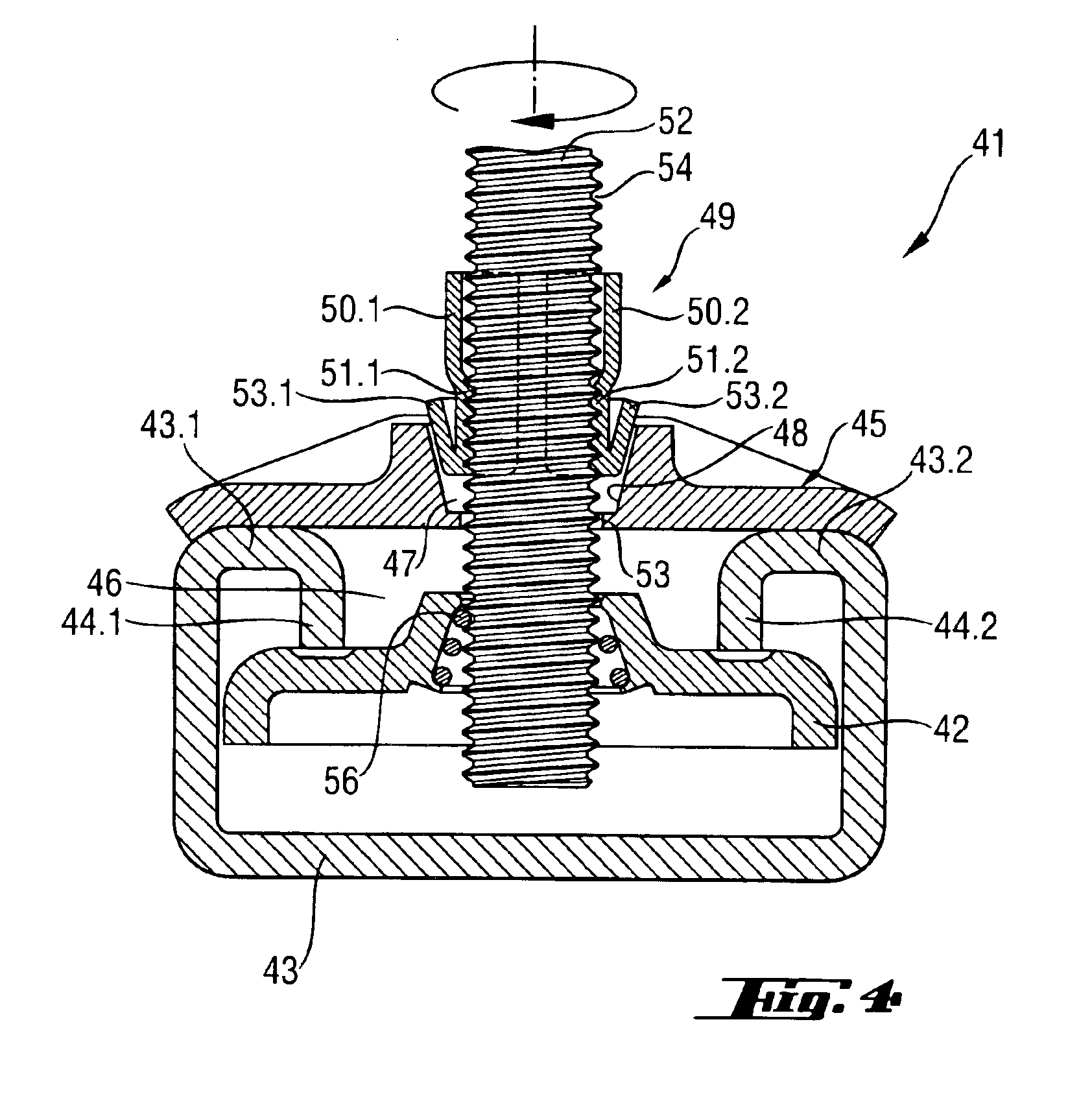
[0016]Preferably, the quick-mountable nut is used for securing a threaded rod on a C-shaped mounting rail. For such use, the base of the quick-mountable nut has a width that is slightly smaller than the opening of the mounting rail, which insures that the nut can be inserted through the opening in the mounting rail. The length of the nut is also somewhat smaller than the inner dimension of the mounting rail. This insures that the quick-mountable nut, which is oriented transverse to the longitudinal axis of the mounting rail, can be formlockingly axially arranged in the mounting rail and can be freely displaced along the mounting rail. The quick-mountable rail can have two axial edges arranged diagonally opposite each other and which are rounded with a diameter corresponding to that of a circle inscribed in the mounting rail. Thereby, the quick-mountable nut, which is inserted along the mounting rail, can be screwed in the mounting rail, e.g., only as a result of a right-hand rotation. Generally, the quick mountable nut, except the above-mentioned axial edges, has a prismatic shape.
[0018]Advantageously, the holding sections of the holding member abut the inner cone wall over their entire surfaces. Thereby, in comparison with a partial abutment by the holding sections, an increased outer restrain is applied to the holding member, which insures a better formlocking fixation of the quick-mountable nut. With the abutment by the holding member over its entire surface, the holding member is so aligned, upon mounting or insertion of the threaded bolt, that a perfect engagement of the holding member with the threaded bolt is achieved. The possibility of tilting of the holding member within the nut housing is completely eliminated.
[0019]Advantageously, the holding sections of the holding member each has an annular middle portion located in a radial plane of the threaded bolt and partially engaging the threaded bolt along is screw thread. The circular middle portions form a thread that can engage in the screw thread of the threaded bolt. Preferably, the circular middle portion is formed by an offset extending radially inward. Preferably, the two arms of the holding member have each an inclination that corresponds to the inclination of the screw thread of the threaded bolt. Thereby, a reliable connection of the outer profile of the threaded bolt with the holding member is insured.
[0021]Advantageously, the quick mountable nut has a cover for covering the nut housing, and has optionally a wedge supported on the cover and extendable radially inward. The wedge is inserted between free ends of the holding sections of the holding member for displacing the holding sections away from each other. The wedge forms unlocking means, that upon insertion between the ends of the holding sections, expands the holding sections against a biasing force. Thereby, the quick-mountable nut can be axially positioned, without being rotated. The wedge provides for both fixation of the quick-mountable nut and its release.
[0023]Advantageously, the nut housing, the cover, and / or the holding member are formed of sheet metal by combined cutting and bending process. Separate parts can be made of suitable plastic material. To meet particular requirements, the elements of the quick-mountable nut can be formed of different materials. To insure a high reliability of attachment or when the quick-mountable nut is used in an aggressive atmosphere, at least the holding member is formed of stainless steel.

Problems solved by technology

However, such forcelocking snappable attachment is not suitable for a screw thread with slopping flanks.
Because of only forcelocking engagement of the wire coil in the screw thread, no stable locking of the nut is possible.
The threaded rod, which is used as a cut member, is cut to a predetermined length, which results in formation of burrs.
The chamfering process and the height adjustment are very time-consuming processes.
The wire coil displacement within the nut housing is such that a perfect engagement of the wire coil with a threaded rod is not possible.

Method used


Image

  • Quick-mountable nut
  • Quick-mountable nut
  • Quick-mountable nut

Examples


Embodiment Construction

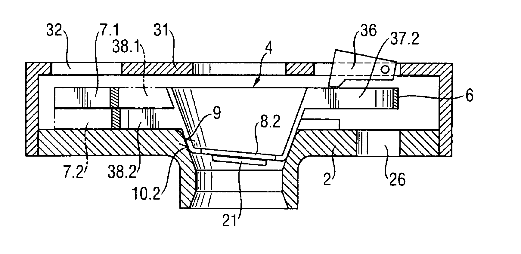
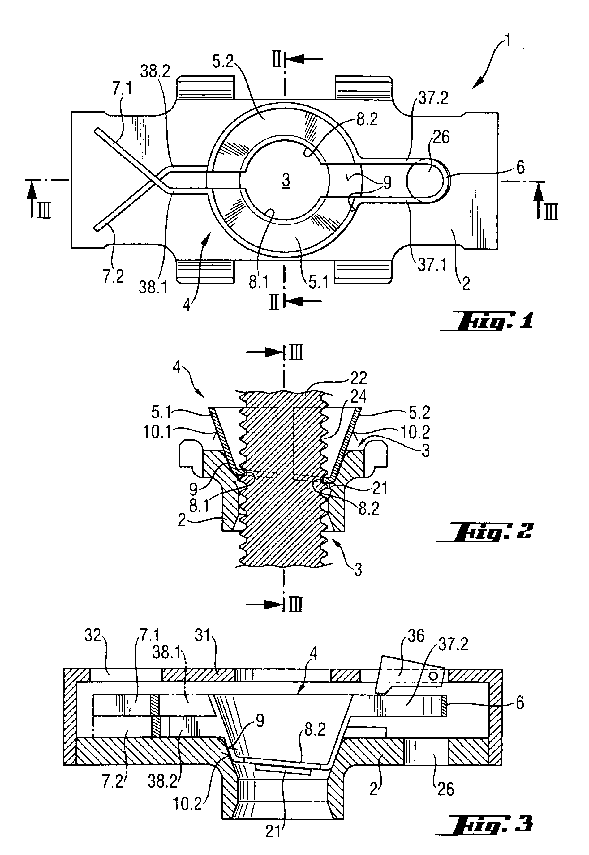
[0030]A quick-mountable nut 1 according to the present invention, a first embodiment of which is shown in FIG. 1, has a nut housing 2 provided with a coaxial through-opening 3. The through-opening 3 has a tapering inner cone 9. A holding member 4 is received in the through-opening 3. The holding member 4 has two springy holding sections 5.1 and 5.2 inclined toward each other and connected with each other at one of their respective ends by a curve element 6. At their free ends, the holding sections 5.1 and 5.2 are provided with cantilever arms 7.1 and 7.2, respectively. The holding sections 5.1 and 5.2 form an outer cone substantially complementary to the inner cone 9 of the opening 3, with outer surfaces 10.1 and 10.2 of the holding sections 5.1 and 5.2 abutting respective surfaces of the inner cone 9.

[0031]When one of the cantilever arms 7.1 and 7.2 is operated upon or both of the cantilever arms 7.1 and 7.2 are simultaneously operated upon, the holding sections 5.1 and 5.2 expand ...


PUM


Abstract

A quick-mountable nut, which is capable of at least partially rotation-free axial displacement relative to a threaded bolt (22; 52), includes a nut housing (2; 45), and a springy holding member (4; 49) at least partially located in the nut housing (2; 45) and engaging in at least one screw thread (24; 54) of the threaded bolt (22, 52), with the central through-opening (3; 47) of the nut housing being formed as a tapering radially inward, inner cone (9; 48) for receiving the holding member (4; 49), and with the holding member (4; 49) having two, resiliently movable relative to each other, holding sections (5.1, 5.2; 50.1, 50.2) having each an even wall section abutting a wall of the inner cone (9, 48).

Description

BACKGROUND OF THE INVENTION[0001]1. Field of the Invention[0002]The present invention relates to a quick-mountable nut capable of at least partially rotation-free axial displacement relative to a threaded bolt and including a nut housing having a central through-opening and a springy holding member at least partially located in the nut housing and engaging in at least one screw thread of the threaded bolt. The central through-opening is formed as an extending radially inward, inner cone for receiving the holding member.[0003]2. Description of the Prior Art[0004]A nut generally has extending radially inward engagement means which formlockingly engages in the outer screw thread of a bolt. The engagement means of the nut provides only for a single degree of freedom of movement of the nut mounted on the bolt, namely, for a screw movement of the nut along the screw thread. The nut is secured on the bolt due to the static friction between the screw thread and the engagement means of the n...

Claims


Application Information

Patent Timeline
IPC IPC(8): F16B37/04F16B37/08F16B37/12F16B37/00
CPCF16B37/045F16B37/0807F16B37/0885F16B37/12
Inventor UNVERZAGT, STEFANHERB, ARMINHOFFMANN, ARMIN
Owner HILTI AG
Learn More