Braided branching stent, method for treating a lumen therewith, and process for manufacture thereof

a branching stent and lumen technology, applied in the field of braided stents, can solve the problems of stent designs having a zig-zag stent architecture, wear in the graft, and larger deployment profile, and achieve the disadvantage of potential graft wear, and the design of zig-zag stents still has the same disadvantag

Inactive Publication Date: 2005-09-13
LIFESHIELD SCI
View PDF41 Cites 60 Cited by
  • Summary
  • Abstract
  • Description
  • Claims
  • Application Information

AI Technical Summary

Benefits of technology

[0016]The braiding may be performed on a braiding machine having a predetermined plurality of bobbin carriers adapted to revolve in a pattern about a longitudinal axis. A first set of bobbin carriers may be adapted to revolve in a first circumferential direction and a second set of bobbin carriers may be adapted to revolve in a second circumferential direction, each bobbin carrier adapted to carry at least one bobbin. Each bobbin is adapted to provide one or more filaments for braiding within the stent. In such case, step (a)(i) comprises using filaments from a first portion of the predetermined plurality of bobbins to braid the first leg about the first detachable mandrel leg positioned substantially along the longitudinal axis in a braiding zone. The braiding zone is defined as a conical zone defined by the filaments extending from the bobbins to the stent on the mandrel. In step (a)(ii), the process comprises using filaments from a second portion of the predetermined plurality of bobbins to braid the second leg about the second detachable mandrel leg positioned in the braiding zone. Step (b) comprises using filaments from both portions of the predetermined plurality of bobbins to braid the body about the mandrel body positioned in the braiding zone.
[0017]Thus, the process may

Problems solved by technology

One potential disadvantage of zig-zag stent architecture is that the apices of the zig-zag structure can rub against the graft, causing wear in the graft.
The formation of the crimp, however, can cause metal cold-work and embrittlement in the stent wires and can result in bulkiness in the bifurcation region, requiring a relatively larger deployment profile than other designs.
One piece stent designs

Method used


Image

  • Braided branching stent, method for treating a lumen therewith, and process for manufacture thereof
  • Braided branching stent, method for treating a lumen therewith, and process for manufacture thereof
  • Braided branching stent, method for treating a lumen therewith, and process for manufacture thereof

Examples


Embodiment Construction

[0052]The entire disclosure of U.S. patent application Ser. No. 09 / 494,704, filed Jan. 31, 2000, is expressly incorporated by reference herein.

[0053]The invention will next be illustrated with reference to the figures wherein similar numbers indicate the same elements in all figures. Such figures are intended to be illustrative rather than limiting and are included herewith to facilitate the explanation of the apparatus of the present invention.

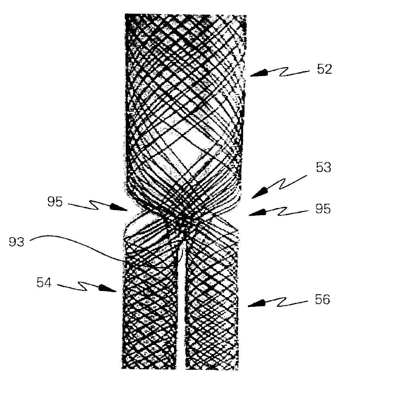
[0054]Referring now to FIG. 3, there is shown a bifurcated, braided stent 50 according to the present invention. As shown in FIG. 3, the stent comprises a trunk section 52, a first iliac leg 54 and a second iliac leg 56. Stent 50 as shown in FIG. 3 is a unitary stent. That is, iliac legs 54 and 56 are continuous with trunk section 52, unlike modular stent designs in which two or more stent segments are assembled together to form the various parts of the stent (e.g., the trunk section and the two legs). As used herein, the term “unitary” means...


PUM


Abstract

A bifurcated, braided stent has a body that branches into a plurality of legs and is adapted for deployment in a lumen. At least a portion of each leg of the stent comprises a discrete plurality of continuous filaments braided together, and at least a portion of the body comprises one or more of the continuous filaments from each of the legs braided together. The stent can be used for treating a diseased bifurcated lumen of a human being by deploying the stent therein. The stent can be constructed by a process comprising braiding each plurality of filaments to form the leg sections, and braiding one or more filaments from each plurality of filaments together to form the body. The process may be performed by creating the legs first and then the body, or vice versa. The stent may be constructed on a mandrel using a braiding machine.

Description

RELATED APPLICATIONS[0001]This application is a divisional of U.S. patent application Ser. No. 09 / 494,704, filed Jan. 31, 2000 now U.S. Pat. No. 6,398,807, which is related to U.S. patent application Ser. No. 09 / 494,980, filed Jan. 31, 2000 (U.S. Pat. No. 6,325,822), titled “BRAIDED STENT HAVING TAPERED FILAMENTS” by Chouinard, Haverkost, Peiffer, and Roberts.TECHNICAL FIELD[0002]This invention relates generally to endoluminal stents, grafts, and / or prostheses and, more specifically, to braided stents adapted for deployment in branched lumina and processes for their manufacture.BACKGROUND OF THE INVENTION[0003]A stent is an elongated device used to support an intraluminal wall. In the case of a stenosis, a stent provides an unobstructed conduit for blood in the area of the stenosis. Such a stent may also have a prosthetic graft layer of fabric or covering lining the inside or outside thereof, such a covered stent being commonly referred to in the art as an intraluminal prosthesis, a...

Claims


Application Information

Patent Timeline
IPC IPC(8): A61F2/06A61F2/00A61F2/82A61F2/90A61L31/00D04C1/06
CPCA61F2/90D04C1/06D04C3/14D04C3/48A61F2002/065A61F2002/821A61F2250/0036A61F2250/0039D10B2509/06A61F2230/001A61F2230/0067
Inventor CHOUINARD, PAUL F.PEIFFER, DENNIS A.HAVERKOST, PATRICK A.
Owner LIFESHIELD SCI
Why Eureka
Try Eureka