
Printed circuit board stiffener

Active Publication Date: 2005-09-13
CONTINENTAL AUTOMOTIVE SYST INC
View PDF15 Cites 17 Cited by
  • Summary
  • Abstract
  • Description
  • Claims
  • Application Information

AI Technical Summary

Benefits of technology

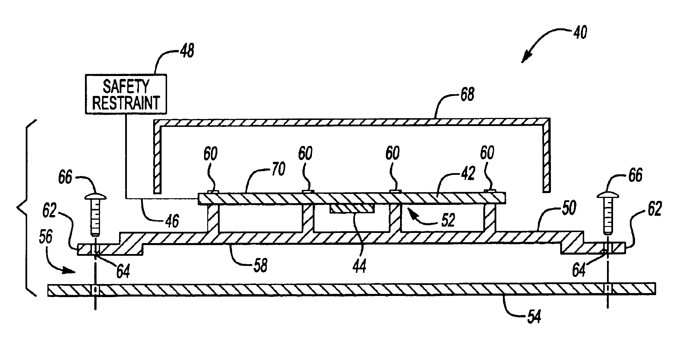
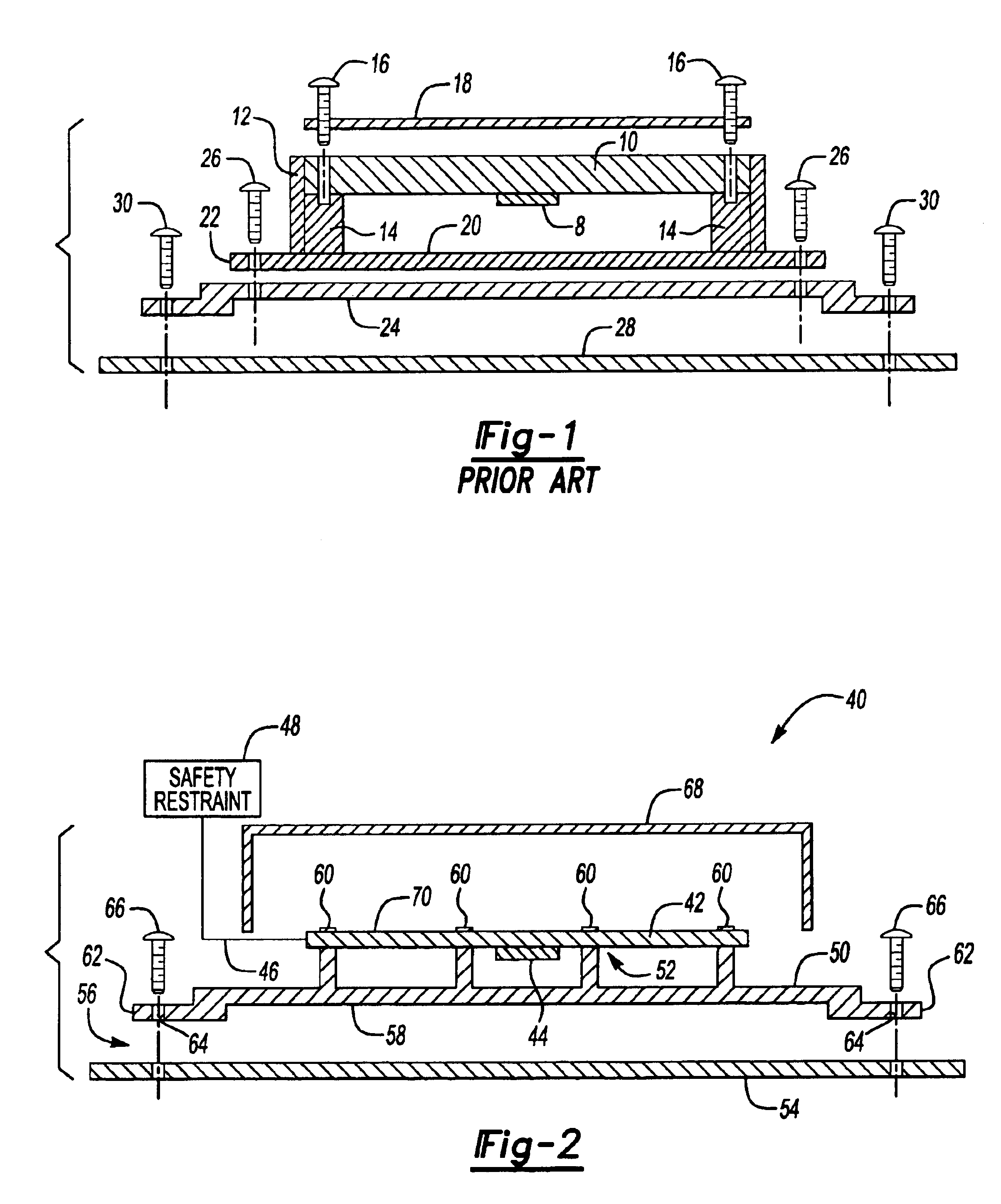
[0010]The subject invention provides a PCB assembly that eliminates the need for a stiff PCB housing, bracket assembly, and a large portion of the mounting hardware traditionally required for mounting a PCB assembly to a vehicle structure. This significantly reduces cost and assembly time along with increased performance of the module by reducing factors that affect the signal performance.

Problems solved by technology

The numerous additional mounting components increase the possibility that the PCB will not be properly secured within the housing unit.
If the PCB is not properly secured or if the screws loosen over time, system accuracy decreases because crash signals will not be properly received by the sensors mounted on the PCB.
Further, these additional mounting components increase the overall component cost, manufacturing cost, and assembly time for the system.

Method used


Image

  • Printed circuit board stiffener
  • Printed circuit board stiffener
  • Printed circuit board stiffener

Examples


Embodiment Construction

[0017]A prior art printed circuit board (PCB) assembly is shown in FIG. 1. The assembly includes a sensor 8 supported on a PCB 10, which is mounted within a PCB housing 12. The PCB housing 12 includes a pair of support walls 14 that support a bottom portion of the PCB 10. A first set of screws 16 mount the PCB 10 to the PCB housing 12. The screws 16 extend through the PCB 10 and into the support walls 14. A cover 18 is positioned over the PCB 10 to enclose the PCB 10 within the PCB housing 12. The first set of screws 16 also secures the cover 18 to the PCB housing 12.

[0018]The PCB housing 12 includes a base portion 20 with a circumferential mounting flange 22. The PCB housing 12 is mounted to a bracket 24 via the mounting flange 22 with a second set of screws 26. The bracket 24 is mounted to a vehicle floor 28 with a third set of screws 30. This traditional configuration requires at least three fastener interfaces, requiring three sets of screws, as wells as requiring a housing, cov...


PUM


Abstract

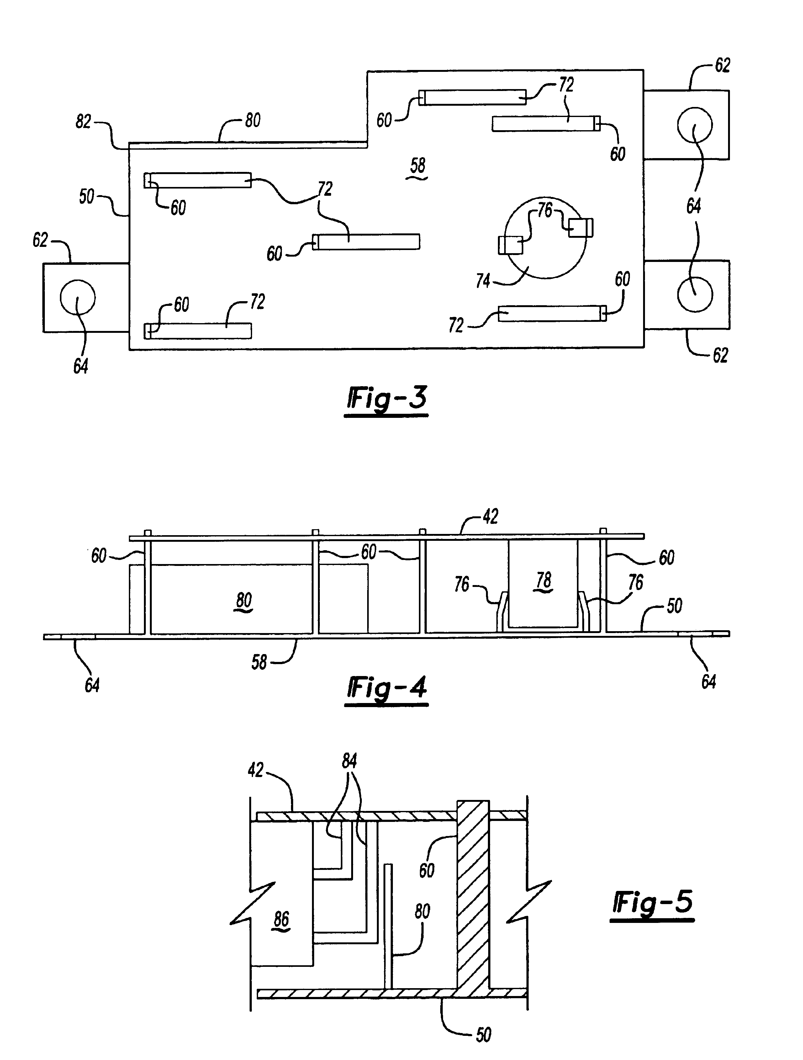
A printed circuit board (PCB) assembly includes a stiffener member that eliminates the need for a separate PCB housing. The stiffener member is attached to the PCB at a first mount interface without the use of fasteners and is attached to a vehicle structure at a second mount interface. The first mount interface comprises a plurality of mounting feet that extend out transversely relative to a stiffener main body portion, and which are soldered directly to the PCB. The second mount interface comprises a plurality of radially extending tabs formed about the circumference of the stiffener member. The tabs each include an aperture for receiving a fastener. The stiffener member also includes gripping elements that resiliently engage electrical components mounted to the PCB to securely hold the electrical component in place and to reduce vibrations.

Description

RELATED APPLICATIONS[0001]The application claims priority to U.S. Provisional Application No. 60 / 469,799, which was filed on May 12, 2003.BACKGROUND OF THE INVENTION[0002]The subject invention generally relates to a printed circuit board (PCB) assembly that eliminates the need for a stiff structure for the PCB housing by mounting a stiffener board directly to the PCB.[0003]Conventional designs for vehicle sensor assemblies, such as safety restraint modules for example, required a very stiff housing unit for a printed circuit board (PCB). The stiff housing unit is required to provide accurate transmission of crash signals from a vehicle to sensors mounted on the PCB. Further, the housing unit supports the PCB in such a manner that the sensors are prevented from receiving false crash signals caused by standard vehicle vibrations. The housing unit also includes an electromagnetic interference (EMI) wall that prevents adjacent electrical systems from interfering with the operation of th...

Claims


Application Information

Patent Timeline
IPC IPC(8): H05K7/14
CPCH05K7/142
Inventor DINGMAN, MICHAEL ALLAN
Owner CONTINENTAL AUTOMOTIVE SYST INC
Learn More