Ignition Coil for Internal Combustion Engine

Active Publication Date: 2012-11-29
HITACHI ASTEMO LTD
View PDF8 Cites 19 Cited by
  • Summary
  • Abstract
  • Description
  • Claims
  • Application Information

AI Technical Summary

Benefits of technology

[0009]In the configuration of JP-8-17657-A, the core portions are held by the press-fitting engaging portion; therefore, the possibility of the positional deviation is low until the resin-molding. However, the coil portion attached to the main core portion is floating before the resin molding using an insulating resin and during the resin molding. Therefore, there is a possibility that the core portions and the coil may deviate due to the action of gravity force, or external force such as the flow-pressure occurring during the pouring of molding resin or molding-strain during the hardening of the resin. Thus, variations in the performance of ignition coils are increased and because of the positional deviation of the coil, excessive force is exerted on a connecting portion be

Problems solved by technology

Since the core holder is provided in JP-2007-194364-A, it has a problem in that assembly man-hours are increased and the cost is increased.
Therefore, there is a possibility that the core portions and the coil may deviate due to the action of gravity force, or external force such as the flow-pressure occurring during the pouring of molding resin or molding-strain during the hardening of the resin.
Thus, variations

Method used


Image

  • Ignition Coil for Internal Combustion Engine
  • Ignition Coil for Internal Combustion Engine
  • Ignition Coil for Internal Combustion Engine

Examples


first embodiment

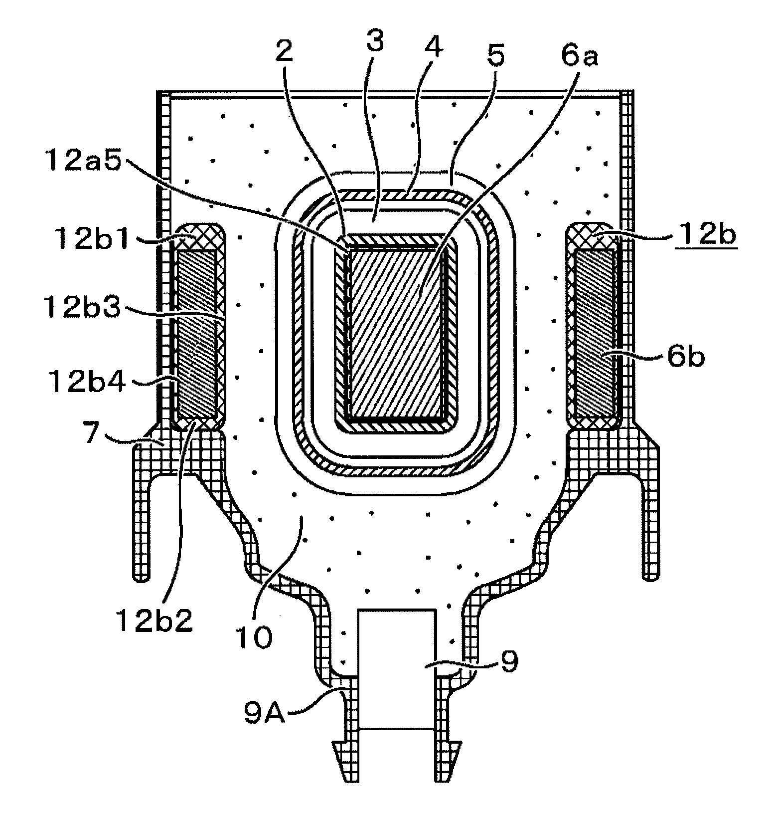
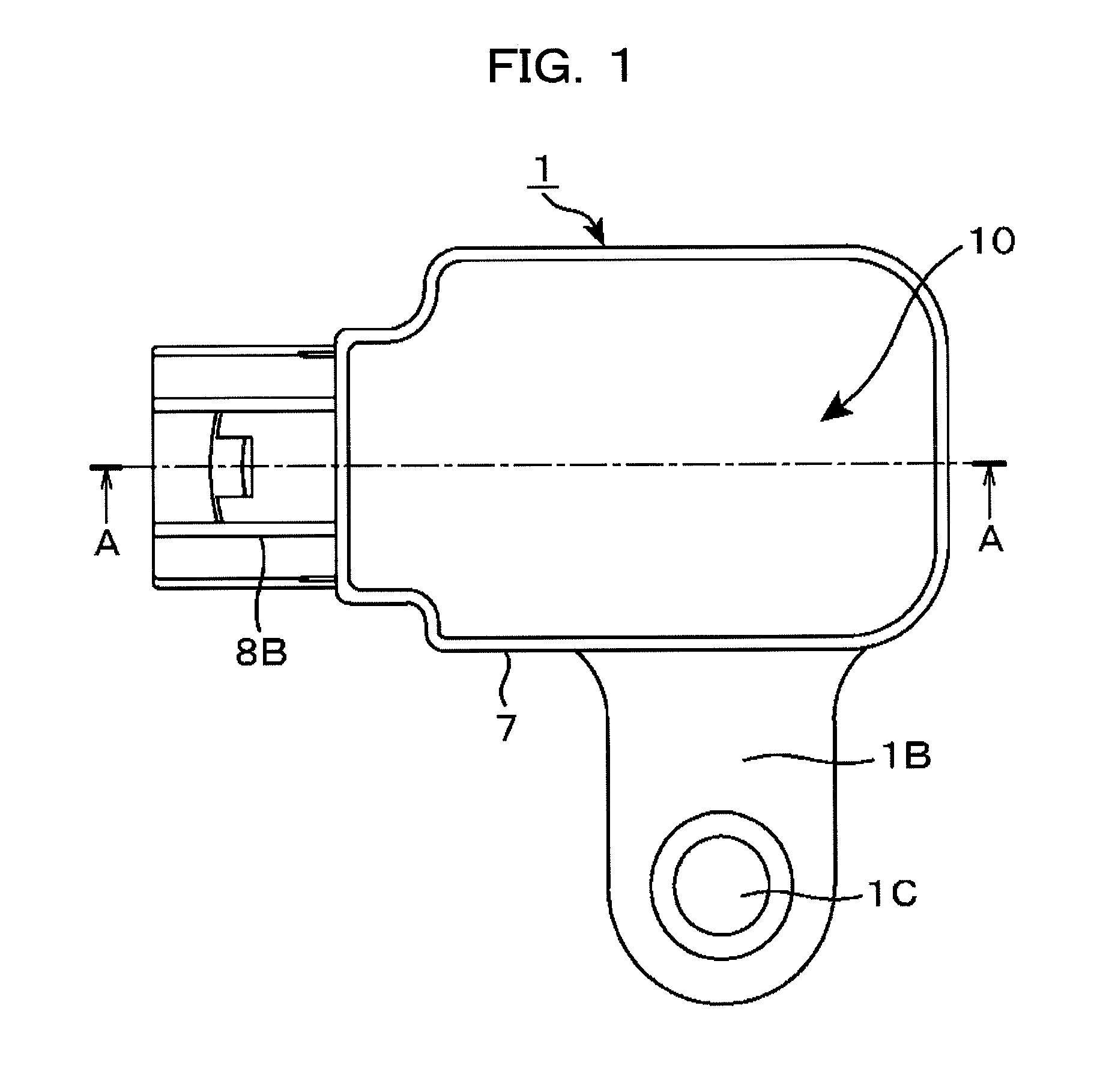
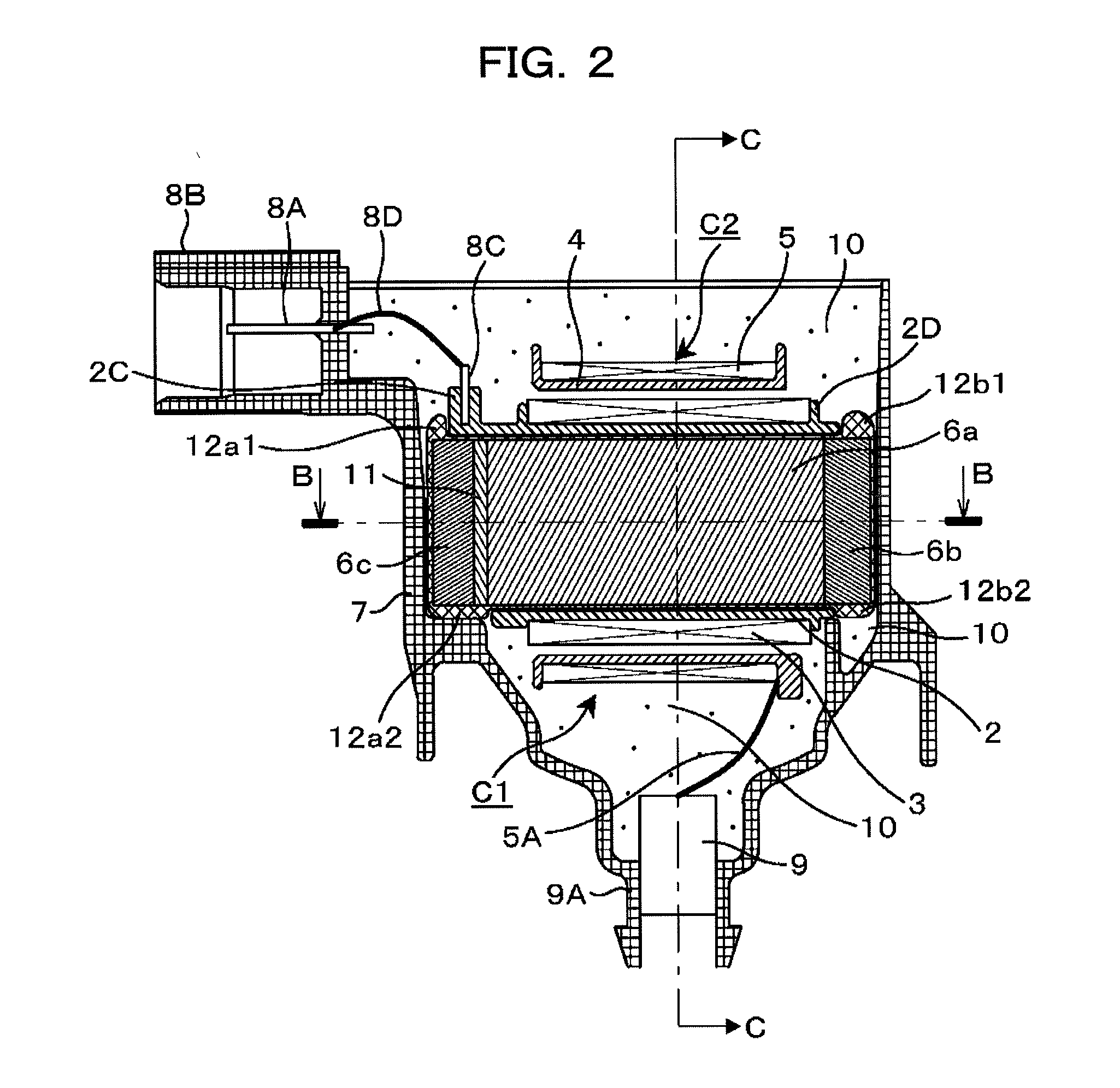
[0036]An ignition coil for an internal combustion engine according to a first embodiment of the present invention is shown in FIGS. 1 to 5 and 10 to 12. FIG. 1 is a top view of an ignition coil for an internal combustion engine according to the present embodiment. FIG. 2 is a cross-sectional view of the ignition coil taken along line A-A in FIG. 1. FIG. 3 is a cross-sectional view of the ignition coil taken along line B-B in FIG. 2. FIG. 4 is a perspective view showing an arrangement shape of iron cores. FIG. 5 is a perspective view showing the iron cores covered by elastic covers. FIG. 10 is a cross-sectional view of the ignition coil taken along line C-C in FIGS. 2 and 3. FIG. 11 is an enlarged view of an upper-left portion of FIG. 3. FIG. 12 is an enlarged view of an upper-right portion of FIG. 3.

[0037]Referring to FIG. 1, an ignition coil 1 has a coil case 7 made of a resinous material.

[0038]The coil case 7 is molded integrally with a connector portion 8B and an attachment flang...

second embodiment

[0069]A second embodiment is hereinafter described with reference to FIGS. 6, 13 and 14.

[0070]In the second embodiment, a main core portion 6a and an auxiliary core portion 6c are punched out as an integral thin steel plate and the integral thin plates are stacked one on another. Therefore, a magnet member is not installed between the main core portion 6a and the auxiliary core portion 6c.

[0071]The coil case 7 is shared by the first embodiment and the second embodiment; therefore, an iron core assembly 6 has the same external dimensions as those of the first embodiment. The second embodiment uses the same coil assembly as that of the first embodiment.

[0072]A core mold 12a8 between an end portion of a primary coil bobbin 2 and the auxiliary core portion 6c is increased in thickness by the thickness of the magnet member 11. In addition, the core mold 12a8 has an outer shape formed to conform to the shape of a projecting portion of the primary coil bobbin 2.

[0073]The main core portion...

third embodiment

[0077]As shown in FIG. 7, an ignition coil according to a third embodiment is configured to have only one side of the side core portion 6b in the first embodiment. In this case, a fitting-recessed portion 6cb is located on a lateral surface of an auxiliary core portion 6c. In addition, a fitting-projection 6bc is located at an end portion of the side core portion 6b corresponding to the fitting-recessed portion 6cb. A fitting-recessed portion 6ab is located on an end lateral surface, of the main core portion 6a, on the side opposite the auxiliary core portion side. In addition, a fitting-projection 6ba is located at an end portion of the side core portion 6b corresponding to the fitting-recessed portion 6ab. The fitting-recessed portion 6cb is fitted to the fitting projection 6bc. The fitting-recessed portion 6ab is fitted to the fitting projection 6ba. Thus, an iron core assembly can be formed.


PUM


Abstract

An auxiliary core portion and a main core portion, including a magnet if the magnet is attached, are covered by a resin film or an elastomer film and fixed as a single assembly. In this state, a coil is attached to the assembly and a side core portion is assembled to the assembly. The auxiliary core portion and the main core portion, including the magnet if it is attached, can be supplied, as the single assembly, to an automated assembly line for ignition coils. It is not necessary to position such components on the assembly line. Thus, the workability of the automated assembly can be enhanced.

Description

BACKGROUND OF THE INVENTION[0001]1. Field of the Invention[0002]The present invention relates to an ignition coil for an internal combustion engine adapted to supply high voltage to an ignition plug of the engine for generating spark discharge. In particular, the invention relates to an ignition coil, for an internal combustion engine, of a type having a main core portion (also called a main yoke portion) to which a coil is attached, and an auxiliary core portion (also called an auxiliary yoke portion) or a side core portion (also called a side yoke portion), the auxiliary core portion or the side core portion being combined with the main core portion to form a closed magnetic path.[0003]2. Description of the Related Art[0004]The ignition coil for an internal combustion engine as described above is configured as below. A coil is attached to a main core portion (some are provided with an auxiliary core portion), and a side core portion is assembled to the main core portion (an auxili...

Claims


Application Information

Patent Timeline
IPC IPC(8): H01F27/00H01F27/02H01F27/24
CPCH01F38/12H01F2038/127
Inventor KOBAYASHI, TAKANOBUANZO, YOICHITAKAHASHI, MAKIO
Owner HITACHI ASTEMO LTD
Why Eureka
Try Eureka