Patrol snooping for higher level cache eviction candidate identification

Inactive Publication Date: 2007-07-19
IBM CORP
View PDF8 Cites 19 Cited by
  • Summary
  • Abstract
  • Description
  • Claims
  • Application Information

AI Technical Summary

Benefits of technology

[0013] The present invention a method and apparatus to increase perform

Problems solved by technology

A problem with the LRU algorithm is that a particular cache line can appear to be not used for a relatively long period of time for two reasons.
Unfortunately, the pseudo random eviction algorithm also of

Method used


Image

  • Patrol snooping for higher level cache eviction candidate identification
  • Patrol snooping for higher level cache eviction candidate identification
  • Patrol snooping for higher level cache eviction candidate identification

Examples


Example

[0030] In the following detailed description of the preferred embodiments, reference is made to the accompanying drawings, which form a part hereof, and within which are shown by way of illustration specific embodiments by which the invention may be practiced. It is to be understood that other embodiments may be utilized and structural changes may be made without departing from the scope of the invention.

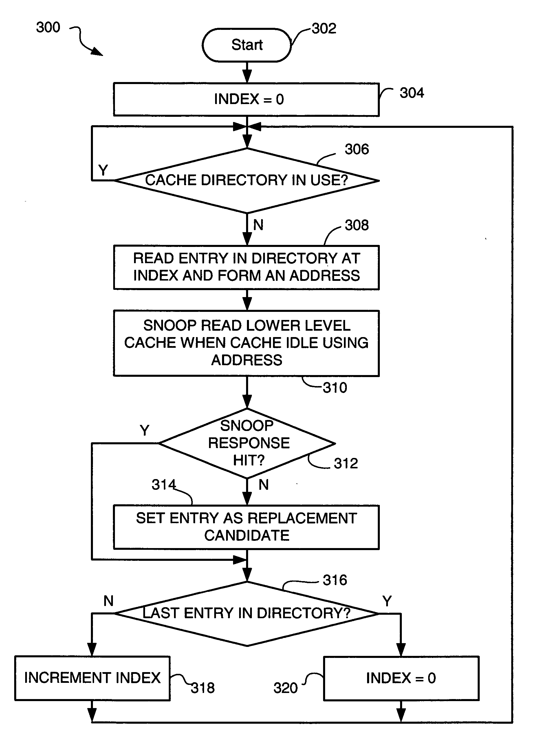
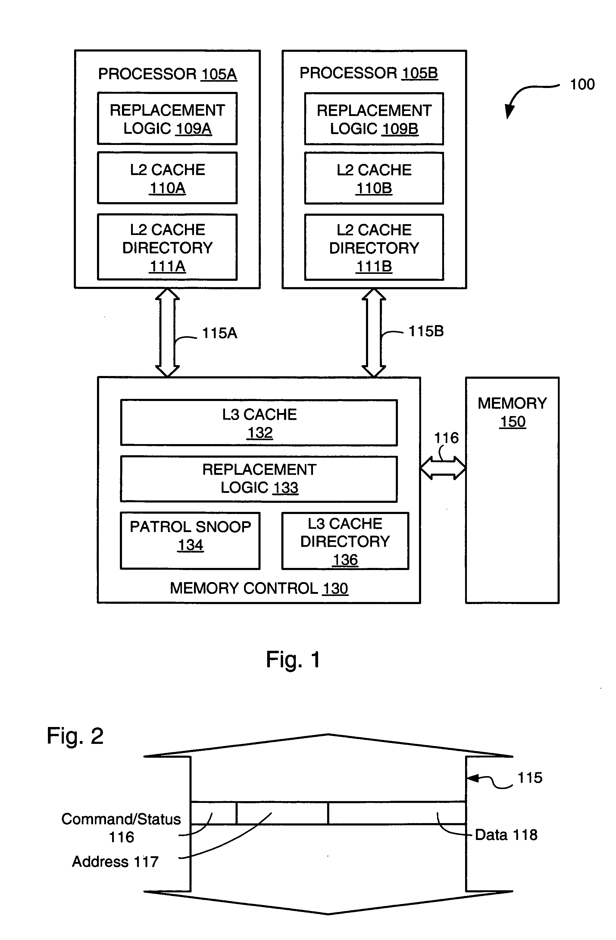
[0031] The present invention provides a method and apparatus to determine eviction candidates in a higher level cache. In a hierarchical cache system (i.e., a cache system having a higher level cache and a lower level cache), all cache lines in a lower level cache also exist in a higher level cache. However, a particular cache line in a higher level cache may not exist in a lower level cache. For example, a processor may request a first data in a first cache line that must be loaded into the lower level cache. The processor reads the first data. Later, the processor may request a s...


PUM


Abstract

A computer system having patrol snoop sequencer that sequences through addresses of cache lines held in a higher level cache, making snoop reads using those addresses to a lower level cache. If a particular cache line held in the higher level cache is not held in the lower level cache, the particular cache line is identified as an eviction candidate in the higher level cache when a new cache line must be loaded into the higher level cache.

Description

BACKGROUND OF THE INVENTION [0001] 1. Field of the Invention [0002] This invention relates generally to multiple levels of cache. More particularly, this invention relates to identifying a cache line in a higher level cache that is a candidate for eviction in the higher level cache when a new cache line must be loaded into the higher level cache. [0003] 2. Description of the Related Art [0004] Modern computer systems typically use multiple levels of cache. For example, a very fast, but relatively small, first level cache is typically implemented on a same semiconductor chip as a processor, and provides data to the processor within one or two processor cycles. The first level cache (L1 cache) is usually implemented using static random access memory (SRAM) that is very fast, but not as compact as larger, slower, memory. The first level cache must be relatively small, also, to limit length of control, address, and signal interconnect. A second level cache (L2 cache) is often also imple...

Claims


Application Information

Patent Timeline
IPC IPC(8): G06F13/00G06F13/28
CPCG06F12/128G06F12/0897
Inventor BORKENHAGEN, JOHN MICHAELVANDERPOOL, BRIAN T.
Owner IBM CORP
Why Eureka
Try Eureka