
Class D Amplifier Having PWM Circuit with Look-up Table

Active Publication Date: 2009-07-02
SYNOPSYS INC
View PDF2 Cites 23 Cited by
  • Summary
  • Abstract
  • Description
  • Claims
  • Application Information

AI Technical Summary

Benefits of technology

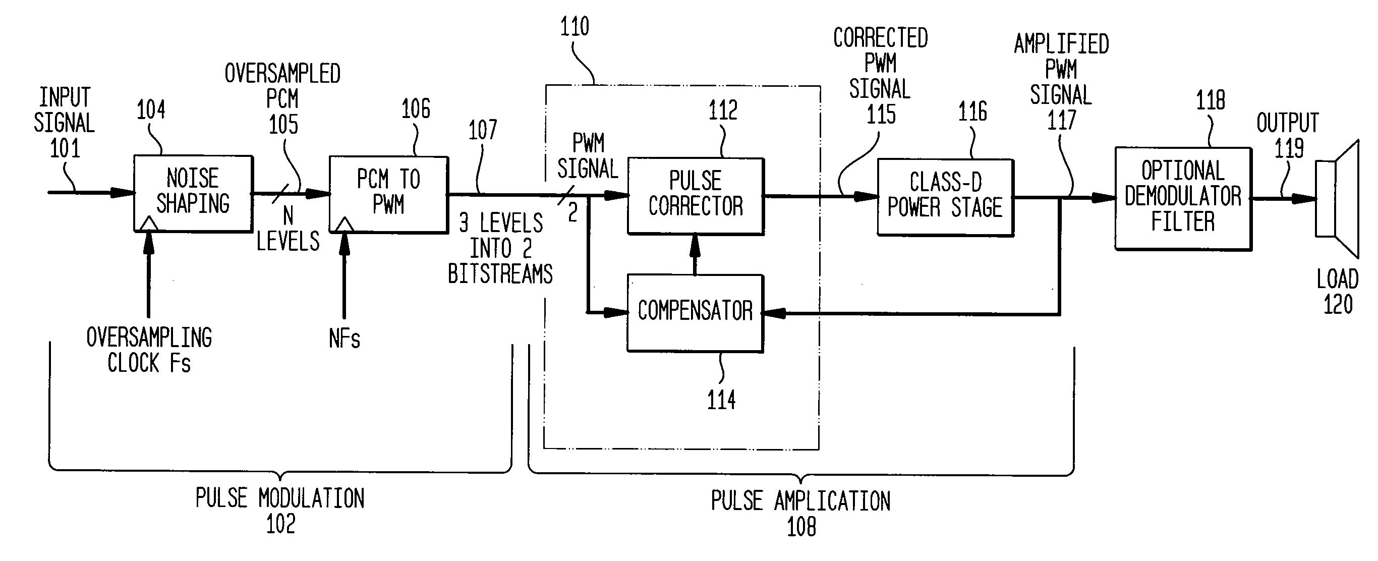
[0018]The amplifier of the invention is a practical solution to the common problems of known class D amplifiers and provides increased performance (e.g., reduced total harmonic distortion (THD)) and increased efficiency (e.g., reduced power consumption). The invention achieves these advantages in an elegantly straightforward way that is area-effective and eliminates the need for complex pre-processing. This allows the amplifier of the application to be easily ported to diverse applications and technologies / processes.

Problems solved by technology

The power efficiency of the driver is dominated by the power stage, and analog amplifiers (e.g., class A, class B and class AB amplifiers) tend to be inefficient.
This results in much lower power loss in the switching transistors of the class D amplifier.
The simplest conceptual architecture is impractical, requiring clock speed in order of GHz for an audio frequency amplifier.
The incorporation of oversampling and noise-shaping techniques can reduce the clock speed down to several tens of MHz, but distortions due to the underlying modulation process are still problematic.
Reported implementations use normal, synchronous modulators that require relatively high switching frequencies to obtain good fidelity but at the expense of power efficiency.
Moreover, despite good modulator designs, an open-loop output power stage will introduce significant distortion and noise.
Their errors are difficult to predict and difficult to eliminate in the digital domain.
The digital PWM modulators normally used for audio applications have distortion problems that can only be solved with complex pre-processing algorithms.
The sigma-delta modulators have noise shaping capabilities but do not offer a fixed frequency output signal as is preferred for class D amplifiers.
Also, only modulators with multi-bit outputs can reach 0 dBFS without stability and distortion issues, but a multi-bit signal is not suitable to feed a class D audio amplifier.

Method used


Image

  • Class D Amplifier Having PWM Circuit with Look-up Table
  • Class D Amplifier Having PWM Circuit with Look-up Table
  • Class D Amplifier Having PWM Circuit with Look-up Table

Examples


Embodiment Construction

[0029]The following detailed description of the invention refers to the accompanying drawings that illustrate exemplary embodiments consistent with this invention. Other embodiments are possible, and modifications may be made to the embodiments within the spirit and scope of the present invention. Therefore, the following detailed description is not meant to limit the invention. Rather, the scope of the invention is defined by the appended claims.

[0030]It would be apparent to one of skill in the art that the present invention, as described below, may be implemented in many different embodiments of hardware, firmware, and / or software (e.g., hardware description language (HDL) such as Verilog). Any actual software and / or hardware described herein is provided by way of example to illustrated the structure and operation of the invention and it not intended to be limiting of the scope of the invention. Thus, the operation and behavior of the present invention will be described with the u...


PUM


Abstract

A class D amplifier includes a noise-shaping modulator, a pulse width modulator, and a pulse amplifier. The noise-shaping modulator receive a pulse code modulated (PCM) signal and produces an oversampled PCM signal. The pulse width modulator produce a pulse width modulated (PWM) signal from the oversampled PCM signal. The pulse amplifier amplifies the PWM signal to produce an amplified PWM signal. The PWM uses a lookup table to convert from PCM to PWM. A compensation circuit optimizes amplifier performance. An optional demodulator filter converts the amplified PWM signal to an analog signal. The amplifier is ideal for integrated audio applications.

Description

BACKGROUND OF THE INVENTION[0001]1. Field of the Invention[0002]This invention relates generally to amplifiers and, more particularly, to a class D audio amplifier.[0003]2. Background Art[0004]Power-hungry linear amplifiers have long dominated the world of audio. But, as portable-electronics consumers demand smaller devices with longer battery life, designers are looking to replace conventional linear amplifiers with high-efficiency, fully-integrated devices. Although class AB amplifiers continue to dominate the world of audio, switch-mode amplifiers are gradually conquering the consumer market, as they provide a good balance between efficiency and distortion.[0005]Integrated circuit technologies favor the implementation of switch-mode audio amplifiers. They also provide means of integrating complex circuits for digital signal processing and power management in a chip.[0006]The power efficiency of the driver is dominated by the power stage, and analog amplifiers (e.g., class A, clas...

Claims


Application Information

Patent Timeline
IPC IPC(8): H03F3/393H03F3/217
CPCH03F3/2173H03F3/187
Inventor GUILHERME, DAVID FILIPE CORREIADUARTE, JORGE MIGUEL ALVES SILVA
Owner SYNOPSYS INC
Learn More