
Advanced electrolytes for high temerature energy storage device

Active Publication Date: 2018-07-26
FASTCAP SYST
View PDF6 Cites 19 Cited by
  • Summary
  • Abstract
  • Description
  • Claims
  • Application Information

AI Technical Summary

Benefits of technology

The patent describes electrolytes for ultracapacitors that contain an ionic liquid and an additive. These electrolytes improve the performance of the ultracapacitor by reducing resistance, increasing capacitance, and increasing energy density. Additionally, they reduce vapor pressure, expand the temperature range in which the ultracapacitor operates, and make it more durable. These improvements make it better than using just the ionic liquid alone.

Problems solved by technology

The electrochemical or other properties of many canisters can cause poor initial performance and lead to premature degradation of the energy storage cell, especially at elevated temperatures.
In fact, a variety of factors work to degrade performance of energy storage systems at elevated temperatures.
One factor that negatively affects EDLC performance at elevated temperatures is the degradation of electrolyte at elevated temperatures.
Moreover, the available electrolytes typically do not perform adequately at temperatures over about 200° C. Certain applications require energy storage cells that are capable of operating at temperatures in excess of about 200° C., e.g., subsurface drilling, such as petroleum exploration and geothermal wells.
Moreover, in certain demanding applications, the available electrolytes do not perform adequately at temperatures over about 150° C. Therefore, electrolytes are needed to extend the operating temperature range of high temperature energy storage cells, particularly EDLCs, to temperatures over about 200° C. Also desirable are electrolytes that are capable of performing over a wide range temperatures, e.g., down to very low temperatures such as −20° C. or even −40° C.
Although typically necessary in any EDLC to prevent contact between the electrodes, the separator frequently introduces undesirable characteristics to EDLCs, e.g., contamination and decomposition.
However, available EDLCs cannot work without a separator to prevent contact between the electrodes, i.e., a short circuit.

Method used


Image

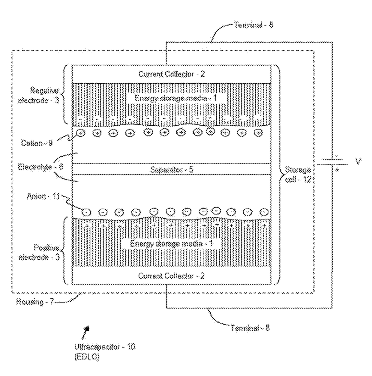
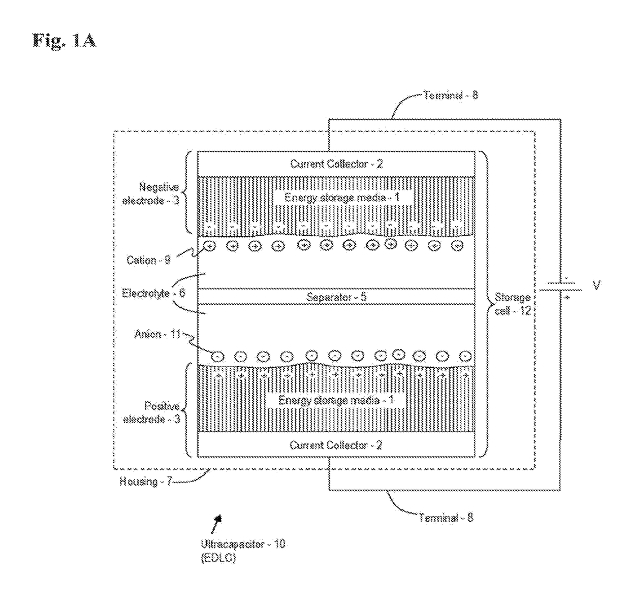
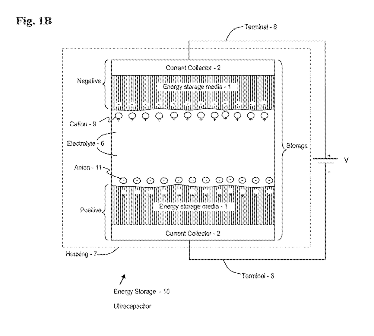
  • Advanced electrolytes for high temerature energy storage device
  • Advanced electrolytes for high temerature energy storage device
  • Advanced electrolytes for high temerature energy storage device

Examples


first embodiment

[0253]With regard to anions 11 suited for use in an ionic liquid that provides the electrolyte 6, various organic anions 11 may be used. Exemplary anions 11 and structures thereof are provided in Table 3. In a first embodiment, (No. 1), exemplary anions 11 are formulated from the list of substitute groups (a) provided above, or their equivalent. In additional embodiments, (Nos. 2-5), exemplary anions 11 are formulated from a respective base structure (Y2, Y3, Y4, . . . Yn) and a respective number of anion substitute groups (α1, α2, α3, . . . αn), where the respective number of anion substitute groups (α) may be selected from the list of substitute (α) groups provided above, or their equivalent. Note that in some embodiments, a plurality of anion substitute groups (α) (i.e., at least one differing anion substitute group (α)) may be used in any one embodiment of the anion 11. Also, note that in some embodiments, the base structure (Y) is a single atom or a designated molecule (as desc...

second embodiment

[0392]Specific examples of glass-to-metal seals that have been used in the ultracapacitor 10 include two different types of glass-to-metal seals. A first one is from SCHOTT with a US location in Elmsford, N.Y. This embodiment uses a stainless steel pin, glass insulator, and a stainless steel body. A second glass-to-metal seal is from HERMETIC SEAL TECHNOLOGY of Cincinnati, Ohio. This second embodiment uses a tantalum pin, glass insulator and a stainless steel body. Varying sizes of the various embodiments may be provided.

[0393]An additional embodiment of the glass-to-metal seal includes an embodiment that uses an aluminum seal and an aluminum body. Yet another embodiment of the glass-to-metal seal includes an aluminum seal using epoxy or other insulating materials (such as ceramics or silicon).

[0394]A number of aspects of the glass-to-metal seal may be configured as desired. For example, dimensions of housing and pin, and the material of the pin and housing may be modified as approp...


PUM


Abstract

An ultracapacitor that includes an energy storage cell immersed in an electrolyte and disposed within an hermetically sealed housing, the cell electrically coupled to a positive contact and a negative contact, wherein the ultracapacitor has a gel or polymer based electrolyte and is configured to output electrical energy at temperatures between about −40° C. and about 250° C. Methods of fabrication and use are provided.

Description

CROSS REFERENCE TO RELATED APPLICATION[0001]The present application claims priority to U.S. Provisional Patent Application No. 61 / 889,018 filed Oct. 9, 2013; U.S. Provisional Patent Application No. 62 / 019,952 filed Jul. 2, 2014; U.S. Provisional Patent Application No. 61 / 925,740, filed Jan. 10, 2014; and U.S. Provisional Patent Application No. 62 / 057,739 filed Sep. 30, 2014, the contents of each of which are incorporated herein by reference.[0002]STATEMENT REGARDING FEDERALLY SPONSORED RESEARCH[0003]This invention was made with government support under Grant No. DE-EE000503 awarded by the U.S. Department of Energy (EERE). The U.S. government has certain rights in the inventionBACKGROUND1. Field of the Invention[0004]The invention disclosed herein relates to energy storage cells, and in particular to techniques for providing an electric double-layer capacitor that is operable at high temperatures.2. Description of the Related Art[0005]Energy storage cells are ubiquitous in our societ...

Claims


Application Information

Patent Timeline
IPC IPC(8): H01G11/56H01G11/36H01G11/24H01G11/52H01G11/68H01G11/70H01G11/80B82Y30/00
CPCH01G11/56H01G11/36H01G11/24H01G11/52H01G11/68H01G11/70H01G11/80B82Y30/00Y02E60/13H01G11/62H01G11/64Y02E60/10H01G11/60H01G11/78
Inventor BRAMBILLA, NICOLO
Owner FASTCAP SYST
Learn More