Beam hopping self addressed packet switched communication system with multiple beam array antenna

a packet switching and beam array technology, applied in the field of satellite communication systems, can solve the problems of limited service to a laydown with a large number of cells, increased cost, complexity, power requirements of satellites, and limited capacity of spot beams

Inactive Publication Date: 2005-09-13
NORTHROP GRUMMAN SYST CORP
View PDF14 Cites 4 Cited by
  • Summary
  • Abstract
  • Description
  • Claims
  • Application Information

AI Technical Summary

Problems solved by technology

Each spot beam provides limited bandwidth.
Yet, as a satellite provides additional simultaneous spot beams, the cost, complexity, and power requirements of the satellite increase.
Thus, the ability to provide service to a laydown with a large number of cells was limited by prior satellite and antenna design and cost considerations.
Circuit switched satellites, however, were generally too inflexible to route such data.

Method used


Image

  • Beam hopping self addressed packet switched communication system with multiple beam array antenna
  • Beam hopping self addressed packet switched communication system with multiple beam array antenna
  • Beam hopping self addressed packet switched communication system with multiple beam array antenna

Examples


Embodiment Construction

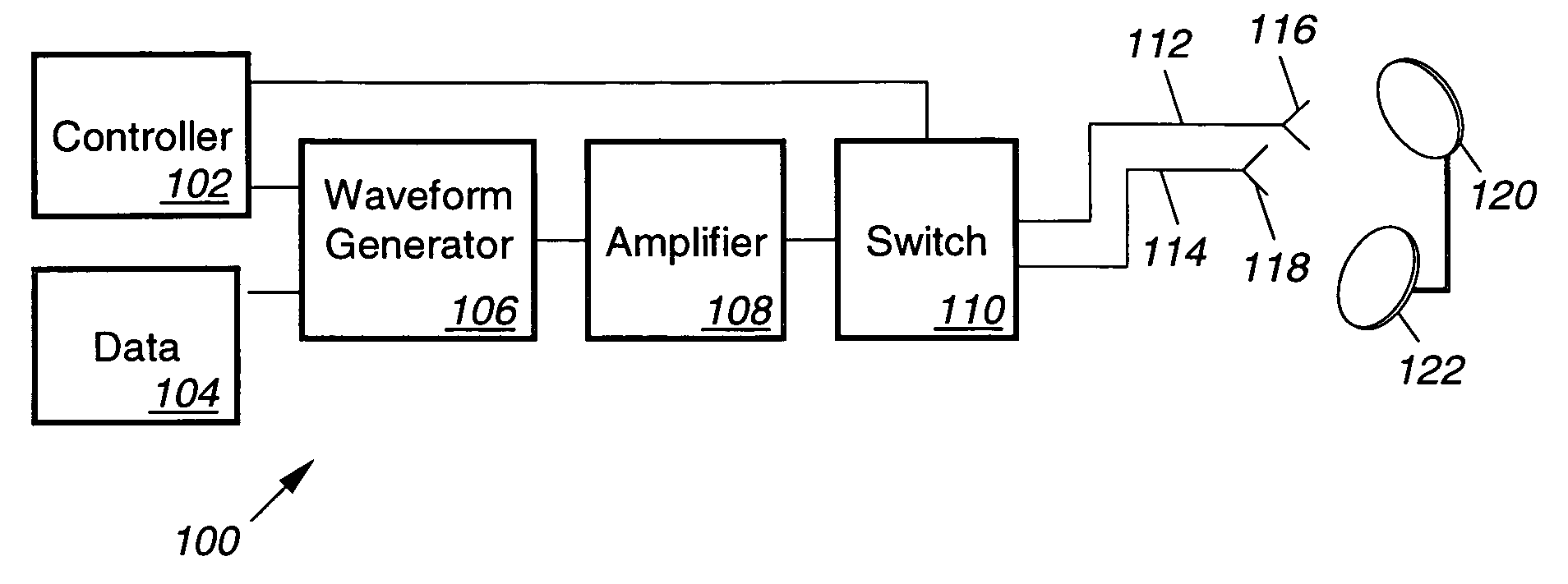
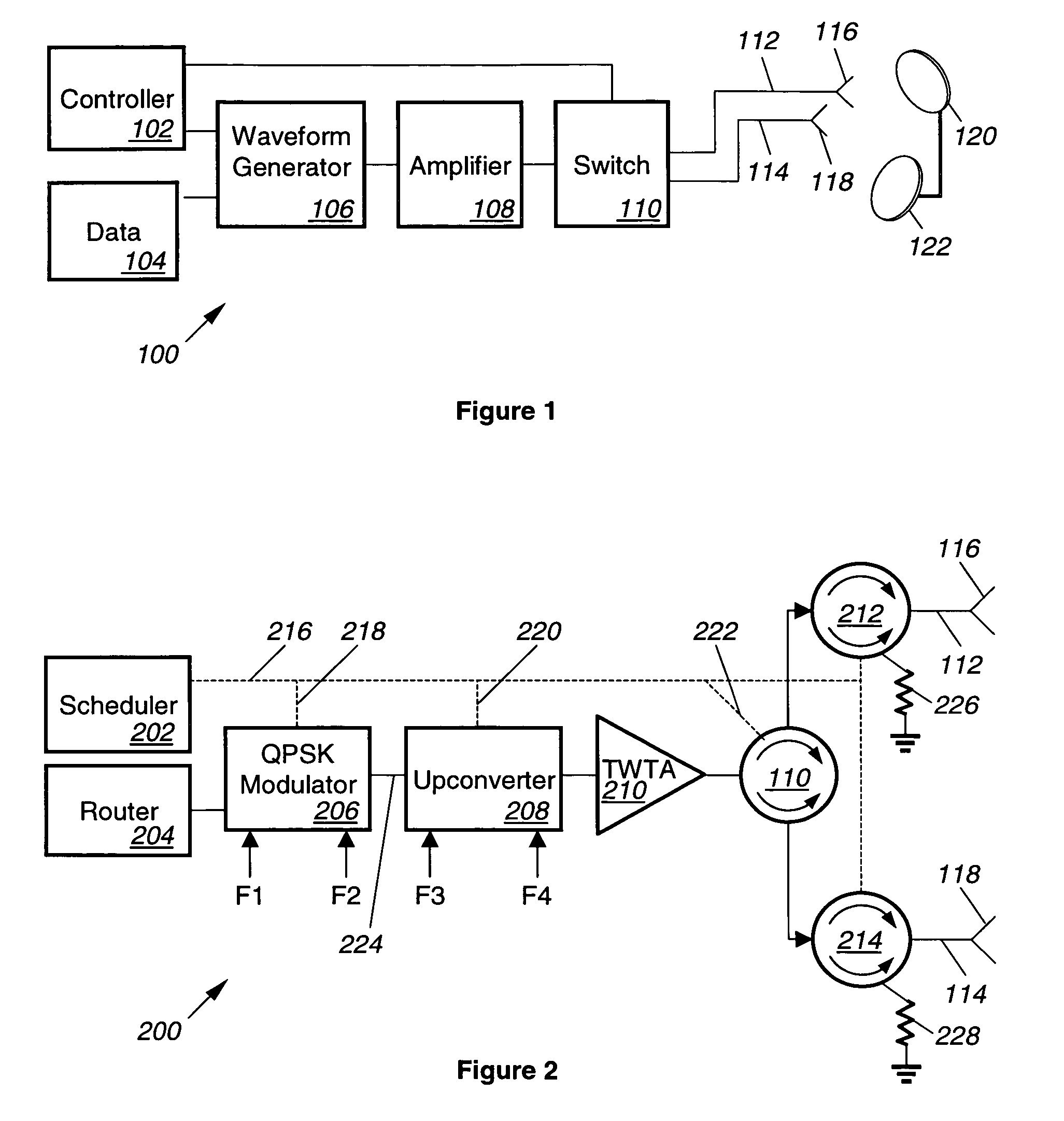
[0025]Turning now to FIG. 1, that figure shows a block diagram of a bandwidth switch 100. The bandwidth switch 100 includes a controller 102 and a waveform processing chain that operates on data provided by the data source 104. In particular, the waveform processing chain includes a waveform generator 106, an amplifier 108, and a switch 110. The waveform processing chain further includes a first feed path 112 and a second feed path 114 that may be characterized by a polarization effect on the waveform that propagates along the feed paths 112–114. The polarization effect may induce, for example, clockwise (right) or counter clockwise (left) polarization in the waveform.

[0026]The first feed path 112 terminates in a first radiating element 116 (e.g., a feed horn). Similarly, the second feed path terminates in a second radiating element 118 (e.g., another feed horn). The first and second feed horns 116, 118 illuminate the subreflector 120. The subreflector 120, in turn, illuminates the ...


PUM


Abstract

A data routing subsystem (200) for a communication satellite includes an inbound module (602) that accepts demodulated uplink data. The inbound module (602) includes a routing table (702) that stores queue tags (714) specifying downlink beam hop locations (302, 304) for the uplink data. The subsystem (200) also includes a self addressed packet switch (608) having an input port coupled to the inbound module (602), and an outbound module (610) coupled to an output port of the switch (608). A memory (804) in the outbound module (610) stores the uplink data in accordance with the downlink beam hop locations (302, 304). A multiple beam array antenna (116–122) is coupled to the outbound module (610). The multiple beam array antenna (116-122) includes a first feed element (116) assigned to a first downlink beam hop location (302) and a second feed element (118) assigned to a second downlink beam hop location (304).

Description

CROSS-REFERENCE TO RELATED APPLICATIONS[0001]This application is related to application Ser. No. 09 / 599,148, filed Jun. 15, 2000, titled “Beam Hopping Self Addressed Packet Switched Communication System with Power Gating; application Ser. No. 09 / 599,041, filed Jun. 21, 2000, titled “Beam Hopping Self Addressed Packet Switched Communication System with Locally Intelligent Scheduling”; and application Ser. No. 09 / 599,035, filed Jun. 21, 2000, titled “Beam Hopping Self Addressed Packet Switched Communication System with Multi-port Shared Memory”.BACKGROUND OF THE INVENTION[0002]The present invention relates to satellite communication systems. In particular, the present invention relates to a satellite communication system including a self addressed packet switch that hops a downlink beam between terrestrial cells using a multiple beam array antenna.[0003]Satellites have long been used to provide communication capabilities on a global scale. For this purpose, a satellite includes multip...

Claims


Application Information

Patent Timeline
Patent Type & Authority Patents(United States)
IPC IPC(8): H04B7/204H04B7/185H04L12/56
CPCH04B7/18515H04B7/2041
Inventor LINSKY, STUART T.BERGER, HARVEY L.NIVENS, DENNIS A.HARMON, GARRICK J.TRAMM, FRED C.WHITE, ROBERT W.
Owner NORTHROP GRUMMAN SYST CORP
Why Eureka
Try Eureka