Register control method

a register and control method technology, applied in the field of register correction in machines, can solve the problems of high cost, inability to meet the needs of the shaft to be corrected, and large startup costs, and achieve the effects of simple startup, small effort and expense for the apparatus, and great synchronicity of the sha

Inactive Publication Date: 2005-09-20
REXROTH INDRAMAT
View PDF14 Cites 3 Cited by
  • Summary
  • Abstract
  • Description
  • Claims
  • Application Information

AI Technical Summary

Benefits of technology

[0008]The object of the present invention is to disclose a method of the type defined at the outset which—particularly when there is a large number of shafts to be regulated

Problems solved by technology

The effort upon startup is accordingly great; furnishing such a high number of individual register regulators is additionally associated with high effort for apparatus and leads to high costs.
Nevertheless, the synchronicity of the shafts to be corrected is not always satisfactory, since intrinsically, mechanically and electronically caused deviations can occur between the individual register regulators

Method used


Image

  • Register control method
  • Register control method
  • Register control method

Examples


Embodiment Construction

[0029]Unless otherwise noted below, all the reference numerals always apply to all the drawings.

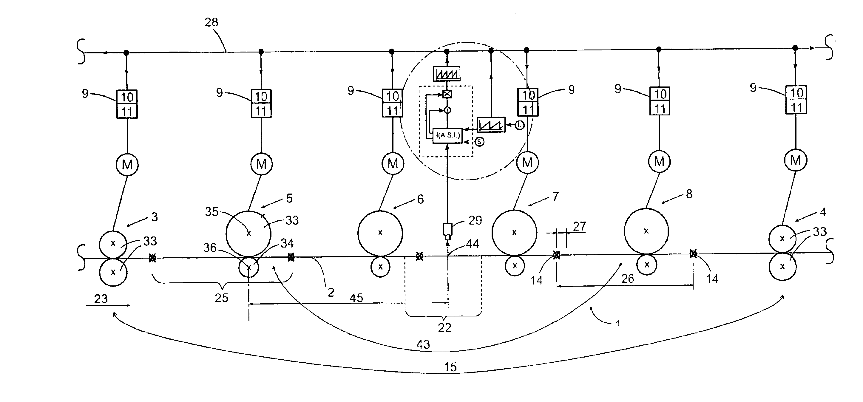
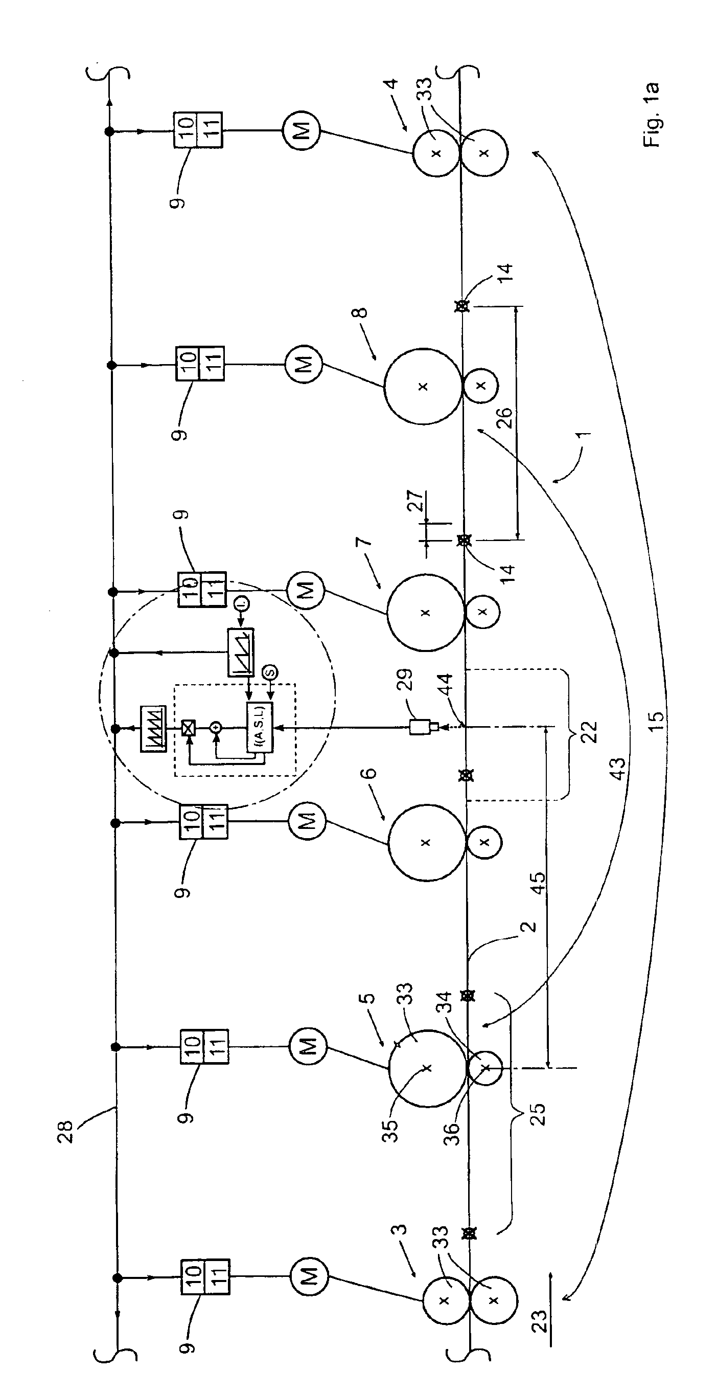
[0030]FIG. 1—in schematically simplified form—shows a processing machine 1 for processing a web of material 2. This is a rotary printing press, comprising a plurality of driven cylinders 33, each with associated contact-pressure cylinders 34.

[0031]The processing machine 1 has an input transport station, which is formed essentially by the transport shaft 3 with its two cylinders 33. On the other end (in terms of the longitudinal direction 23), there is an output transport shaft 4, again comprising two cooperating cylinders 33. Between the transport shafts 3, 4, there are four processing stations 5, 6, 7, 8, hereinafter for the sake of simplicity simply called processing shafts 5, 6, 7, 8.

[0032]The term “shaft” will be used here for the corresponding station with the associated cylinders 33, their motors M, and the associated drive mechanism 9. The term “shaft” should be distinguished in pa...


PUM


Abstract

A method for register correction in machines for processing webs of material includes providing at least one transport shaft and at least one processing shaft cooperating with the at least one transport shaft, driving the shafts synchronously with one another each by an individual drive mechanism, obeying by at least one shaft a chronological guide shaft function which corresponds to an instantaneous position of a guide shaft, correcting a plurality of register-tracking shafts formed by the transport shafts in accordance with a scan of register marks or the web of material relative to the guide shaft function, effecting only one common scanning for one group of the register-tracking shafts which correspond to one another in term of the register correction, and deriving from the only one common scanning a common correction function that all of the register-tracking shafts of the group obey.

Description

BACKGROUND OF THE INVENTION[0001]The invention relates to a method for register correction in machines that process webs of material.[0002]Such a machine has transporting and processing stations, for instance with appropriate driven cylinders. In this respect, for the sake of simplicity, merely their shafts will be referred to.[0003]Such methods are employed for instance in rotary printing presses, paper processing machines or sheet-fed printing presses, when an already-processed or -printed web of paper is to be further processed or printed (insetting), so that the subsequent processing steps must be done at a longitudinal position that is oriented precisely relative to an imprint that has already been made on the paper web. This assures that for instance two successively applied printed motifs will coincide in the predetermined relative position on the paper. To achieve this, cooperating transport shafts and processing shafts are corrected relative to one another by means of the r...

Claims


Application Information

Patent Timeline
IPC IPC(8): B41F13/004B41F13/12B41F13/08B41F33/06B41F33/14
CPCB41F13/0045B41F13/12
Inventor SCHULTZE, STEPHANDOERES, HANS-JUERGEN
Owner REXROTH INDRAMAT
Why Eureka
Try Eureka