Wet clutch or friction plate brake

Active Publication Date: 2005-09-20
BORG WARNER INC
View PDF5 Cites 21 Cited by
  • Summary
  • Abstract
  • Description
  • Claims
  • Application Information

AI Technical Summary

Benefits of technology

[0025]If the balance piston is designed and positioned in accordance with the invention, then the volume of the oil space in the area of the inner wall of the clutch hub is reduced. Thereby a supplemental positive or forced oil flow occurs, which further supports the oil transport to the friction plates of the friction pack.
[0026]For increasing the stiffness and therewith providing an improvement of the hydraulic-mechanical ability of the tota

Problems solved by technology

Although an arrangement of this type has essentially proven itself as useful, with this type of arrangement a complete compensation of centrifugal forces is only possible at great expense.
T

Method used


Image

  • Wet clutch or friction plate brake
  • Wet clutch or friction plate brake
  • Wet clutch or friction plate brake

Examples


Example

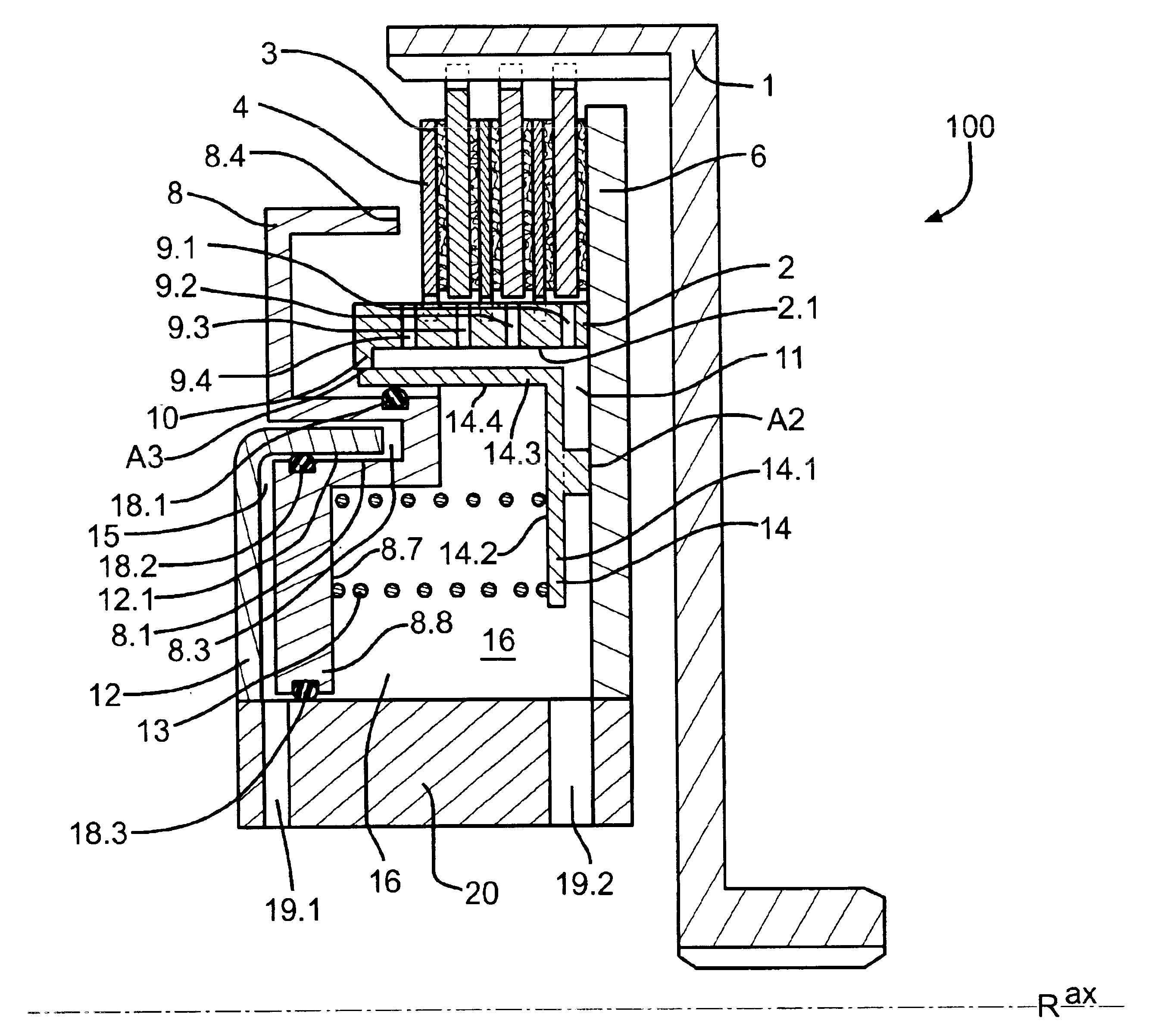
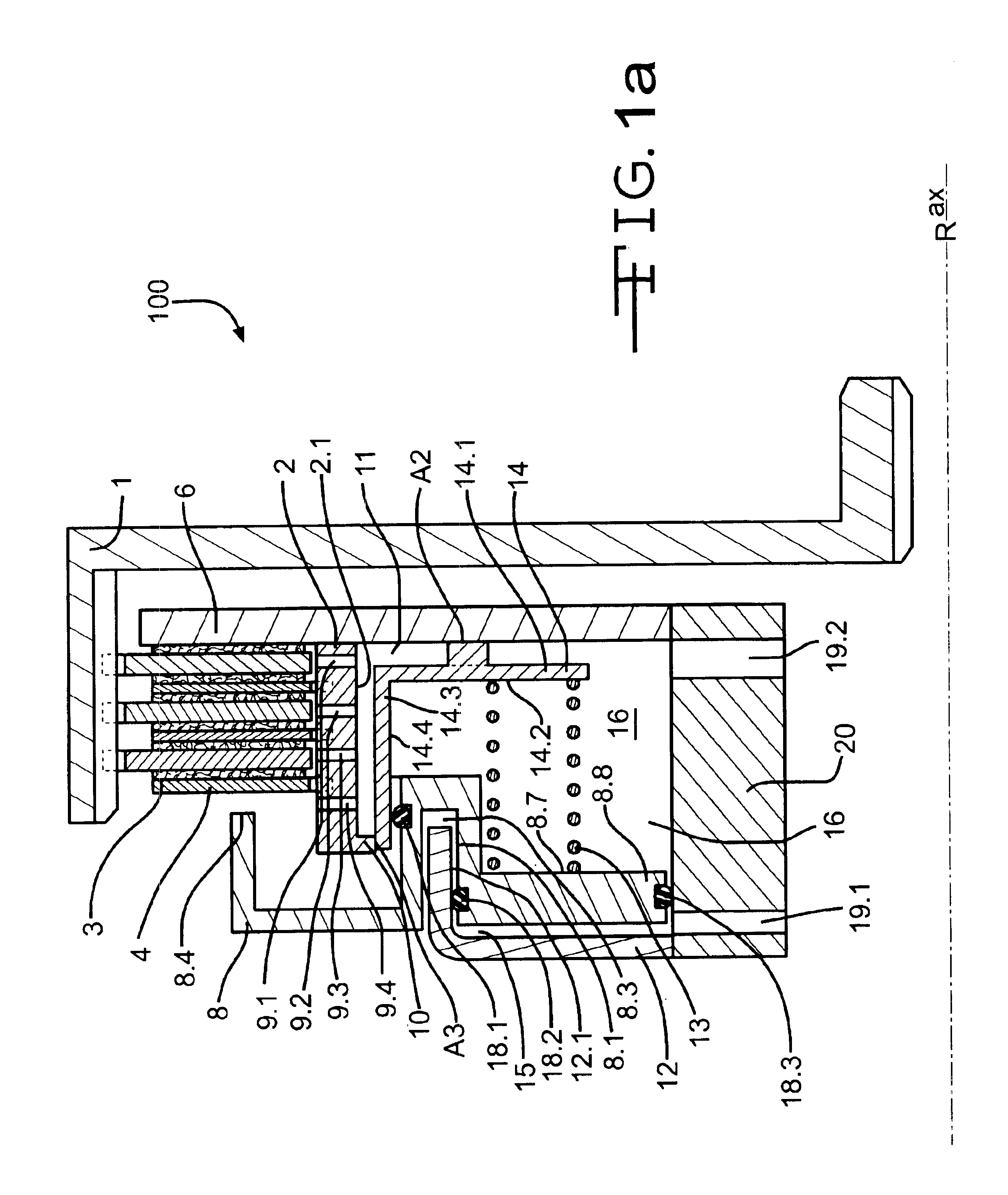
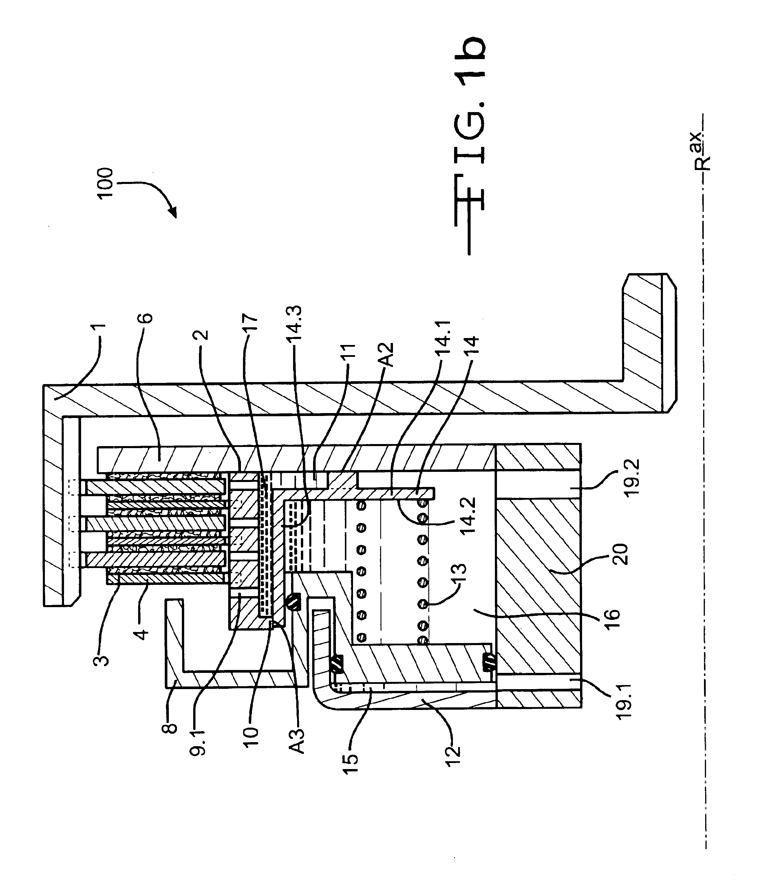
[0040]The subject matter of the invention will be described below on the basis of a side-by-side comparison of a wet clutch of an automatic transmission according to the state of the art as shown in FIG. 2 and a wet clutch of an automatic transmission according to the invention as represented in FIG. 1. It should however be noted that the invention is concerned in general with force transmission aggregates of the type which employ for force transmission a friction pack with multiple friction plates (at least two friction plates), which intermesh or interdigitate in manner of gear teeth, wherein respectively adjacent friction plates can be brought into frictional contact with each other by means of a suitable actuating device.

[0041]As can be seen from illustration FIG. 2a, a wet clutch 200 of an automatic transmission is comprised of a clutch housing 21 mounted rotatably about a rotation axis R, essentially in the shape of a hollow cylinder, as well as a clutch hub 22 provided at lea...


PUM


Abstract

Wet clutch (100) or friction plate brake has an essentially hollow cylindrical shaped balance piston (14) that is coaxial to a clutch hub (2) and is rigidly connected with an apply piston support device (12), an essentially ring shaped spring support (14.1), and an essentially cylinder shaped wall (14.3) that has an essentially cylinder shaped contact surface (14.4). The cylinder shaped contact surface (14.4) is axially (ax) displaceable and is bordered by an essentially cylinder shaped contact surface (8.5) of an apply piston (8) so as to form an equalizing space (16). The contact or support surfaces (14.4, 8.5) of the balance piston (14) and the apply piston (8) are provided coaxial between the clutch hub (2) and the apply piston support device (12).

Description

BACKGROUND OF THE INVENTION[0001]The invention concerns a wet clutch or a friction plate brake according to the pre-characterizing portion of Claim 1.[0002]In this field a generic wet clutch or friction plate brake is generally comprised of a clutch housing, a clutch hub, various outer and inner friction plates, an apply piston and an apply piston support device for carrying the apply piston. All the above-mentioned construction components are as a rule formed essentially rotation-symmetrically and are provided coaxially about a common (rotation) axis.[0003]The clutch housing is essentially in the form of a hollow cylinder and is mounted rotatably about the rotation axis. It carries one or more outer friction plates, wherein these are essentially displaceable or slideable in the axial direction.[0004]In similar manner the clutch hub is also essentially in the form of a hollow cylinder and is mounted rotatably about the same rotation axis. This also carries one or more preferably rin...

Claims


Application Information

Patent Timeline
IPC IPC(8): F16D25/06F16D25/00F16D25/12F16D25/0638F16D13/64F16D55/36
CPCF16D25/0638F16D25/12F16D13/64
Inventor SCHMIDT, THOMAS
Owner BORG WARNER INC
Why Eureka
Try Eureka