
Carrying bag for a brass instrument

a technology for carrying bags and brass instruments, applied in the direction of rigid containers, covers, accessories, etc., can solve the problems of insufficient protection against physical impact, relatively heavy carrying bags of this type, and no protection from side blows, etc., and achieve the effect of high stability

Inactive Publication Date: 2005-09-20
DIMBATH WOLFGANG
View PDF11 Cites 8 Cited by
  • Summary
  • Abstract
  • Description
  • Claims
  • Application Information

AI Technical Summary

Benefits of technology

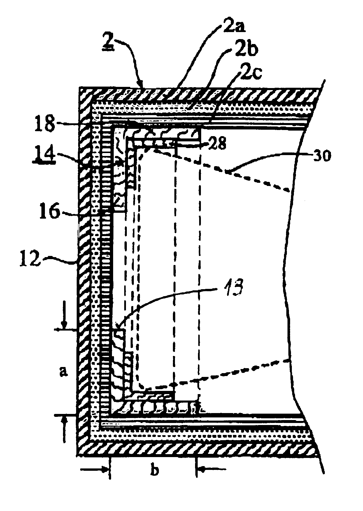
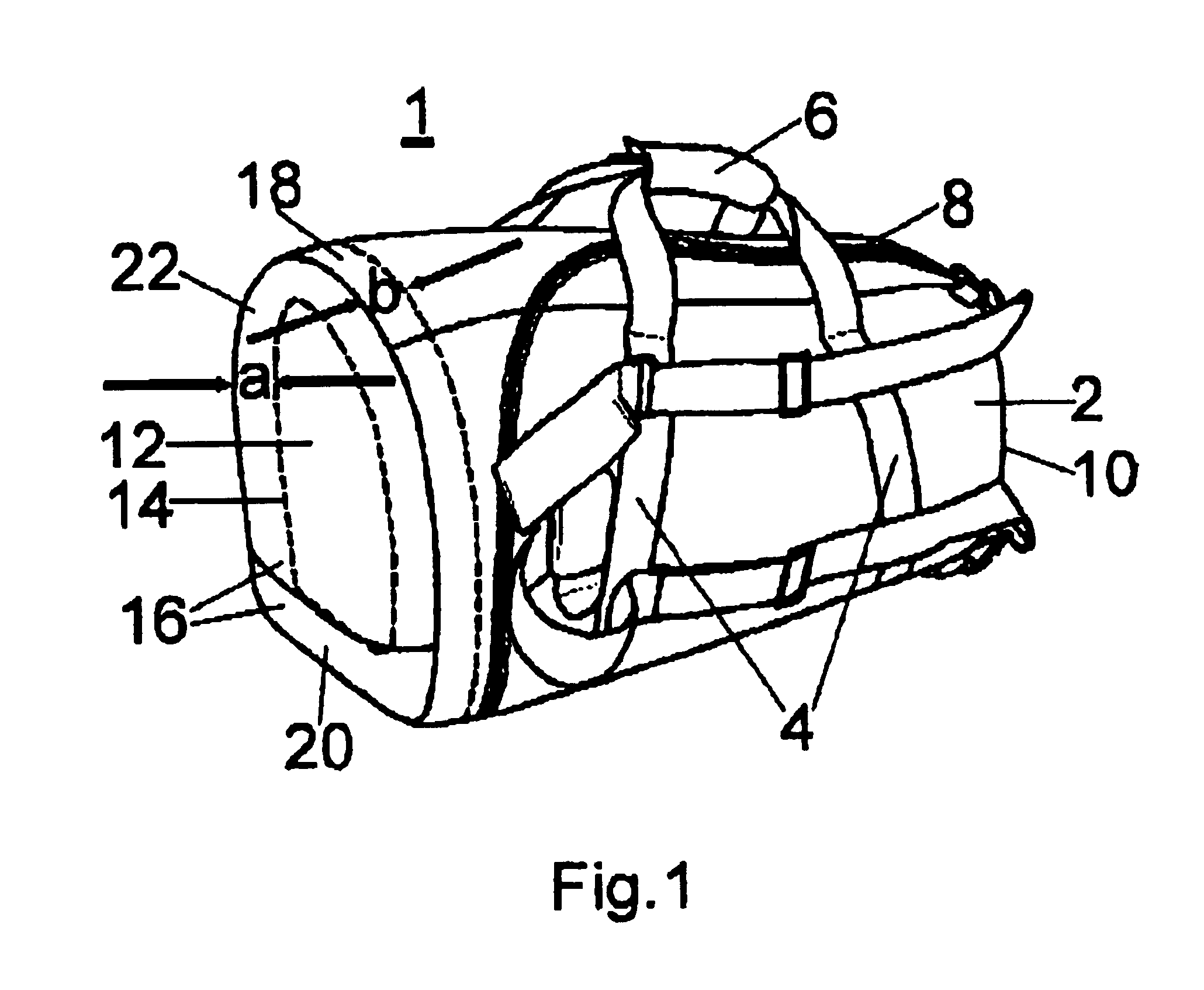
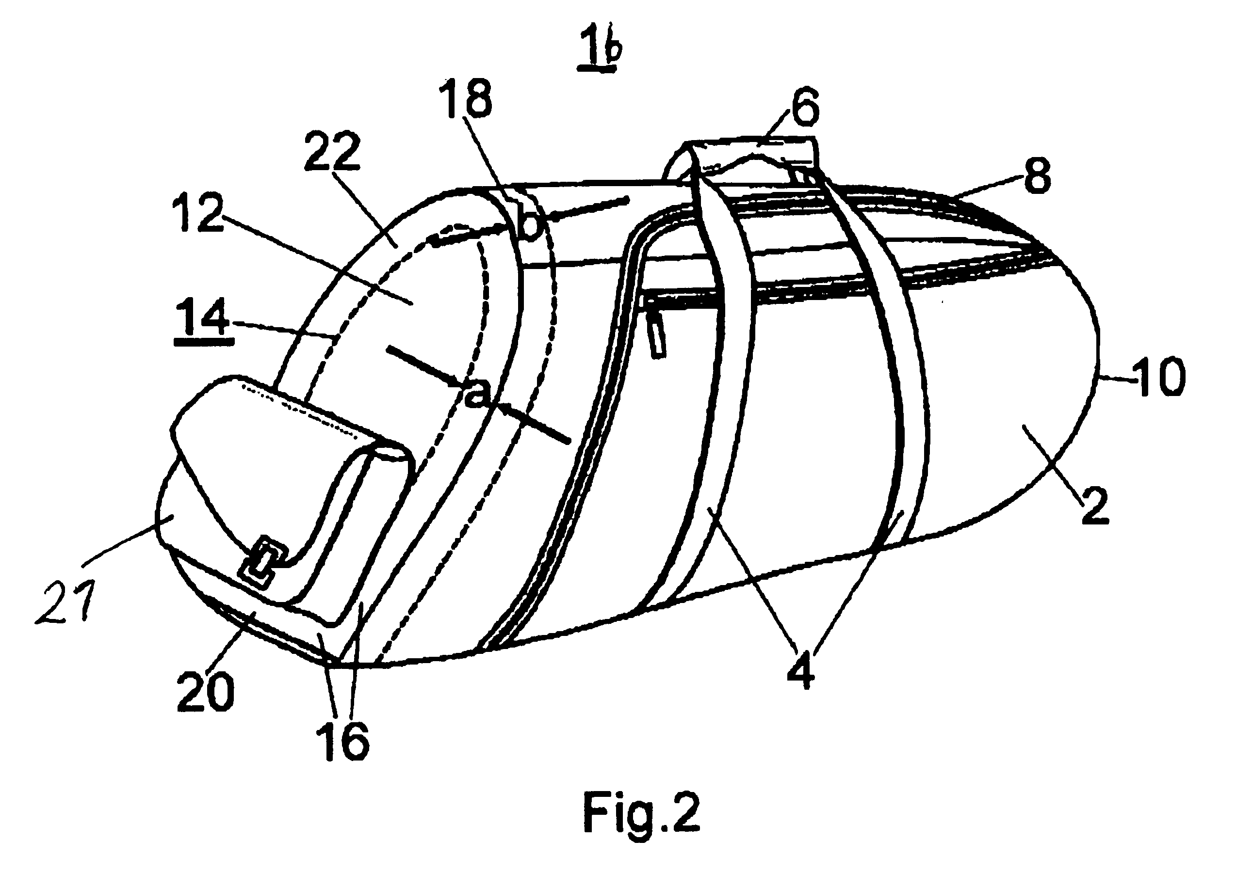
[0009]The present invention resolves prior art problems by providing a frame on the inside of the shell at the front or end portion in the area of the bag edge for reinforcement of the flexible shell. While an effective protection of the brass instrument is realized from impacts, blows, also from the side or even from the rear, or when the carrying bag is put down hard on a surface, the overall weight of the carrying bag is barely increased. The carrying bag according to the present invention exhibits an increased strength of the shell through incorporation of the frame. Such a frame can be produced very cost-efficiently, and inserted even at a later time, and does not significantly increase the weight of the carrying bag.
[0012]According to another feature of the present invention, the stiffening frame may include a ring-shaped closed end piece and a rim portion attached all-round about the end piece and pointing toward the interior of the shell. In this way, the carrying bag is especially well-protected against blows and provides a protection of the bell rim against blows and impacts from the side or even from the rear.
[0014]The contour of the end piece can be made dependent on the shape of the end portion of the shell. Thus, the end piece may be circular, or according to another feature of the present invention, the end piece may include a straight bottom strip and a U-shaped arcuate strip which is arranged onto the bottom strip. Such configuration results in a high stability when the carrying bag is placed on a ground.

Problems solved by technology

The need to reconcile a sufficient protection with a desire for a lightest possible construction of the carrying bag poses a problem heretofore.
While suitable for stabilizing the contour of the shell, the wire is insufficient to protect against physical impact.
A carrying bag of this type is relatively heavy.
Moreover, while the incorporated plates may provide protection against impacts that strike the respective end surface in a direction perpendicular to the plate, they afford no protection against blows from the side.
Thus, the rim of the bell of, e.g., a trumpet placed into the carrying bag, is still exposed to a risk of damage by blows.

Method used


Image

  • Carrying bag for a brass instrument
  • Carrying bag for a brass instrument
  • Carrying bag for a brass instrument

Examples


Embodiment Construction

[0022]Throughout all the Figures, same or corresponding elements are generally indicated by same reference numerals. These depicted embodiments are to be understood as illustrative of the invention and not as limiting in any way. It should also be understood that the drawings are not necessarily to scale and that the embodiments are sometimes illustrated by graphic symbols, phantom lines, diagrammatic representations and fragmentary views. In certain instances, details which are not necessary for an understanding of the present invention or which render other details difficult to perceive may have been omitted.

[0023]Turning now to the drawing, and in particular to FIG. 1, there is shown a schematic perspective illustration of one embodiment of a carrying bag according to the present invention, generally designated by reference numeral 1, for transport of a brass instrument such as an euphonium or trumpet. The carrying bag has a shell 2 which is provided on both longitudinal sides wi...


PUM


Abstract

A carrying bag for a brass instrument includes a shell made of flexible material and having opposite end portions. A transport member, e.g. a handle, is secured to the shell. Arranged in the interior of the shell at one of the end portions adjacent to a bell of a brass instrument is a closed stiffening frame which is made of a firm material. The stiffening frame includes a ring-shaped closed end piece and a rim portion attached all-round about the end piece and pointing toward the interior of the shell.

Description

CROSS-REFERENCES TO RELATED APPLICATIONS[0001]This application claims the priority of German Patent Application, Serial No. 102 57 516.9, filed Dec. 10, 2002, pursuant to 35 U.S.C. 119(a)-(d), the disclosure of which is incorporated herein by reference.BACKGROUND OF THE INVENTION[0002]The present invention relates, in general, to a carrying bag for a brass instrument.[0003]A brass instrument, such as a trumpet, tuba, bugle, trombone or euphonium, is a very sensitive and generally precious musical instrument. Therefore, when not in use, the brass instrument must be protected in a case. During transport, brass instruments are placed in a padded carrying bag having a transport member, such as carrying straps and / or handles. While carrying bags for brass instruments should provide adequate protection, there should also be of light-weight construction so that the user is not unduly inconvenienced, when carrying the bag with the instrument. The need to reconcile a sufficient protection wi...

Claims


Application Information

Patent Timeline
Patent Type & Authority Patents(United States)
IPC IPC(8): A45C11/00A45C11/24A45C5/00A45C5/06A45C13/30
CPCA45C5/06A45C11/24A45C13/30
Inventor DIMBATH, WOLFGANG
Owner DIMBATH WOLFGANG
Learn More