Connecting structure for electric wire to shield case of apparatus

a technology of connecting structure and shield case, which is applied in the direction of coupling/case, vehicle connector, coupling device connection, etc., can solve the problems of inability to regard the constitution as excellent in operability and the number of parts is liable to increase, and achieves a high seal effect and reduces the number of parts.

Inactive Publication Date: 2005-09-20
AUTONETWORKS TECH LTD +2
View PDF12 Cites 66 Cited by
  • Summary
  • Abstract
  • Description
  • Claims
  • Application Information

AI Technical Summary

Benefits of technology

[0016]According to the invention, in at least one of the housings, the plurality of housings are integrally formed and therefore, a number of parts can effectively be reduced.
[0017]According to the invention, the electric connection is carried out by the connecting member at the external portion of the electric wire side housing and therefore, it is not necessary to provide a structure for the connection at inside of the electric wire side housing and an inner structure thereof can be simplified and therefore, (specifically, the inner structure can be constituted as a smooth inner peripheral face and therefore,) when the seal member for sealing the shield electric wire and the electric wire side housing are provided at the inner portion of the electric wire side housing, a constitution having a high seal effect is constructed.

Problems solved by technology

Meanwhile, there is provided a shield connector of a prior art in which terminals are fixed by a bolt at inside of a shield case and according to such a constitution of connecting the terminals by fastening the bolt, there are needed an opening portion constituting an operating port for fastening the bolt, a lid for closing the opening portion to waterproof, a number of parts is liable to increase and the constitution cannot be regarded to be excellent in operability.

Method used


Image

  • Connecting structure for electric wire to shield case of apparatus
  • Connecting structure for electric wire to shield case of apparatus
  • Connecting structure for electric wire to shield case of apparatus

Examples


embodiment 1

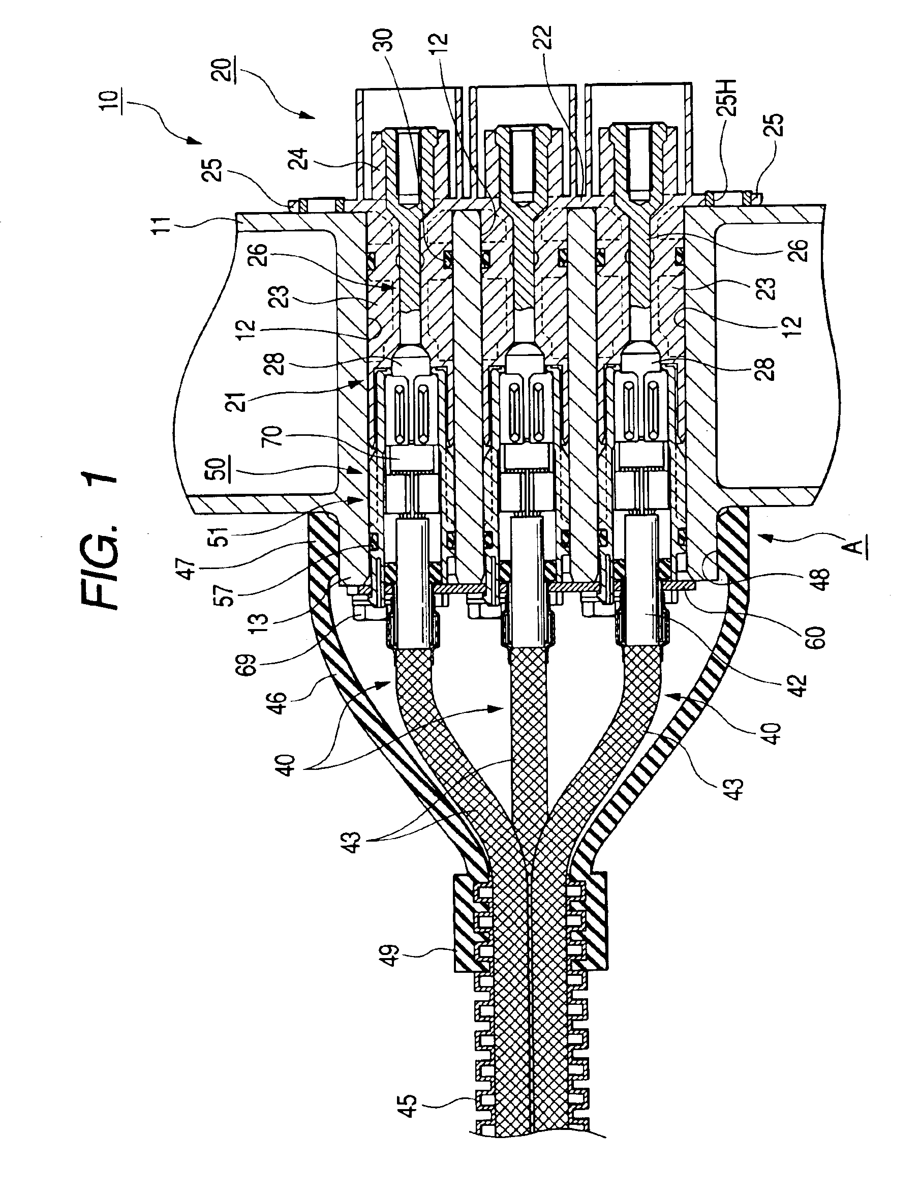
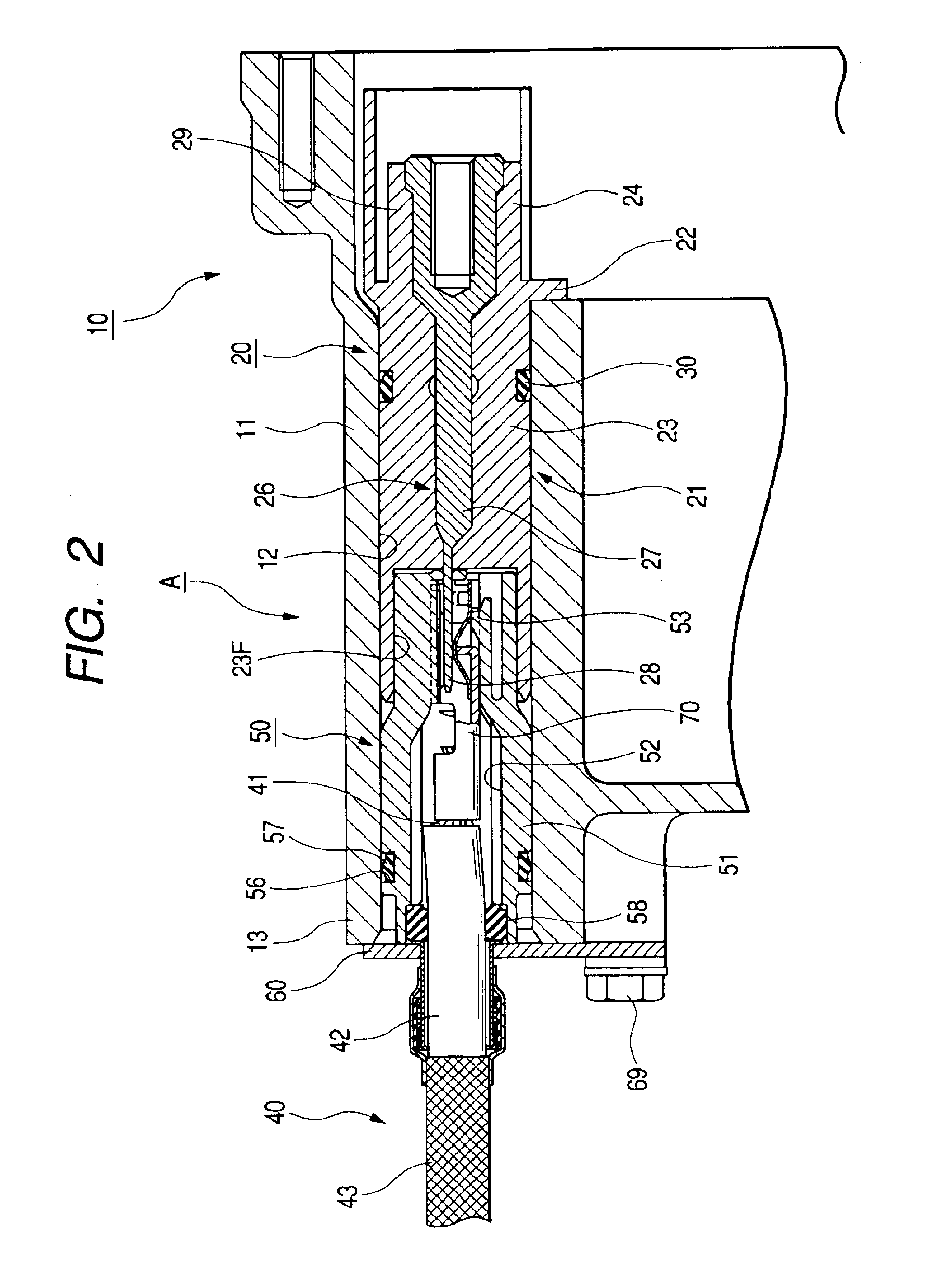
[0027]An explanation will be given of Embodiment 1 embodying the invention in reference to FIG. 1 through FIG. 9 as follows.

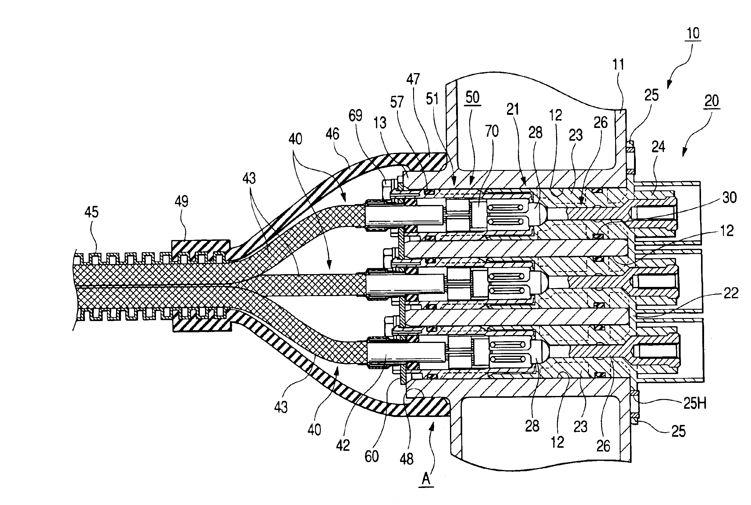
[0028]As shown by FIG. 1 and FIG. 2, in a structure A of connecting an electric wire to a shield case of an apparatus according to the embodiment, an electric wire side connector 50 is connected to a distal end portion of a conductor 41 constituting a core line of a shield electric wire 40, a shield layer 43 of the shield electric wire 40 is connected to a shield case 11 of an apparatus 10 (for example, an inverter apparatus of an electric car), and an electric wire side terminal 70 provided at the electric wire side connector 50 is connected to an electric wire side terminal 26 at inside of the shield case 11.

[0029]The apparatus 10 is constituted by containing an apparatus main body (not illustrated) at inside of the conductive shield case 11 and containing an apparatus side connector 20 connected to the apparatus main body similarly at inside of the shield ca...

first embodiment

[0055](2) Although according to the above-described embodiment, the apparatus side housing is constituted in the mode in which a plurality of housing elements are integrally continuous, similar to the electric wire side housing of the first embodiment, there may be constituted a constitution in which respectively independent housings are inserted into the respective attaching holes.

[0056](3) Although according to the above-described embodiment, the apparatus side terminal is integrated to the apparatus side housing by insert molding, there may be constituted a state of inserting the apparatus side terminal to the apparatus side housing to contain.

[0057](4) Although according to the above-described embodiment, there is constituted the state of inserting the electric wire side terminal to the electric wire side housing to contain, according to the embodiment, the electric wire side terminal and the electric wire side housing may be integrated by insert molding.

[0058](5) Although accor...


PUM


Abstract

Therein is provided with a connecting structure to the shield case of an apparatus so that a number of the connector parts are decreasing and that connecting operation is facilitated. The connector includes a insulative first housing fixed in a state of being inserted into a through hole, a first terminal held by the housing to face the through hole and connected to the electric circuit. The second housing of the electric wire side is fitted to the first housing. The second terminal is connected to the first terminal. Sealing rings are provided between the outer periphery of the housings and the through hole on outer periphery of the housings so that the bracket fixed to the shield case is electrically connected to shield layer of the shield electric wire. A connecting member electrically connects the bracket and the shield layer outside of the second housing.

Description

BACKGROUND OF THE INVENTION[0001]1. Field of the Invention[0002]The present invention relates to a structure of connecting an electric wire to a shield case of an apparatus.[0003]2. Description of the Related Art[0004]There is used a structure of connecting an electric wire to a shield case for connecting apparatus of an inverter apparatus, a motor and the like in, for example, electric motor. There is an electric wire connecting structure of this kind in which an electric wire side terminal is fixedly connected to an end portion of a conductor of a shield electric wire, the electric wire side terminal is connected to an apparatus side terminal provided at inside of a shield case of an apparatus and a shield layer of the shield electric wire is connected to a shield case via a conductive connecting member (refer to, for example, JP-A-2002-125348).[0005]Meanwhile, there is provided a shield connector of a prior art in which terminals are fixed by a bolt at inside of a shield case and...

Claims


Application Information

Patent Timeline
Patent Type & Authority Patents(United States)
IPC IPC(8): H01R9/05H01R13/648H01R13/52
CPCH01R9/0521H01R13/6485H01R13/5208H01R2201/26
Inventor MIYAZAKI, SHOAIHARA, HIROSHISASAKI, KEI
Owner AUTONETWORKS TECH LTD
Why Eureka
Try Eureka