
Cushioned pivoting deck

Inactive Publication Date: 2005-09-20
PRECOR
View PDF23 Cites 10 Cited by
  • Summary
  • Abstract
  • Description
  • Claims
  • Application Information

AI Technical Summary

Benefits of technology

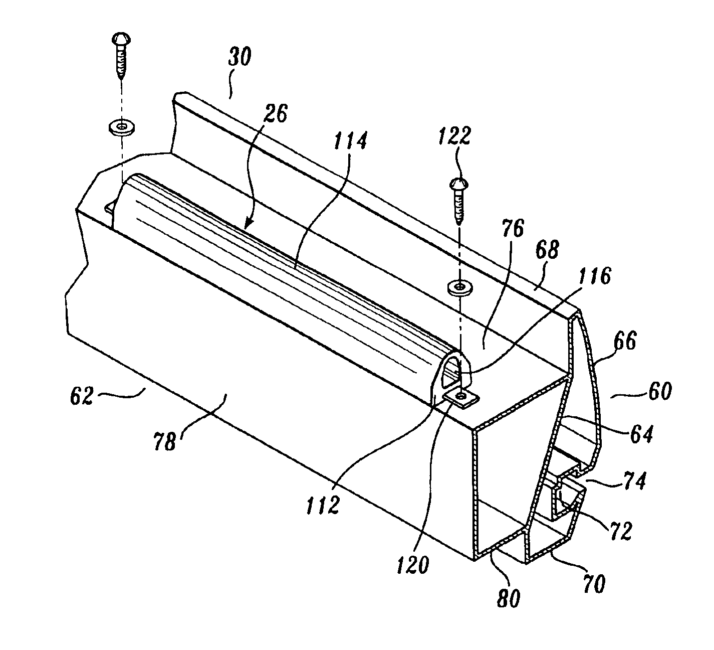
[0011]In an additional aspect of the present invention, the wall thickness of the body portion of the elastomeric spring is greater at the intersection of the body portion with the base of the elastomeric spring. The wall thickness of the body portion decreases in the direction away from the base portion, reaching a minimum thickness at the top of the domed body portion. As a result, when the deck imparts a downward load on the elastomeric springs, the top central portion of the body portion of the elastomeric spring deflects downwardly into the hollow interior, rather than the body portion deflecting sideways, which could occur if the elastomeric spring was of solid construction. Also, the resistance imposed on the deck by the elastomeric spring increases as the deck deflects downwardly, thereby providing a variable rate spring.

Problems solved by technology

Striding on a deck results in pivoting of the lever arms and extension of the shock absorbers, thereby to dampen the impact of the user's feet.
A drawback of this shock absorption system is its complex nature, rendering it costly to manufacture.
Placement of the spring and shock absorber at the very front of the deck imposes considerable bending stress on the deck.
One drawback of this particular treadmill construction is that the elastomeric springs are fixed in place and individually define a rather small bearing area.

Method used


Image

  • Cushioned pivoting deck
  • Cushioned pivoting deck
  • Cushioned pivoting deck

Examples


Embodiment Construction

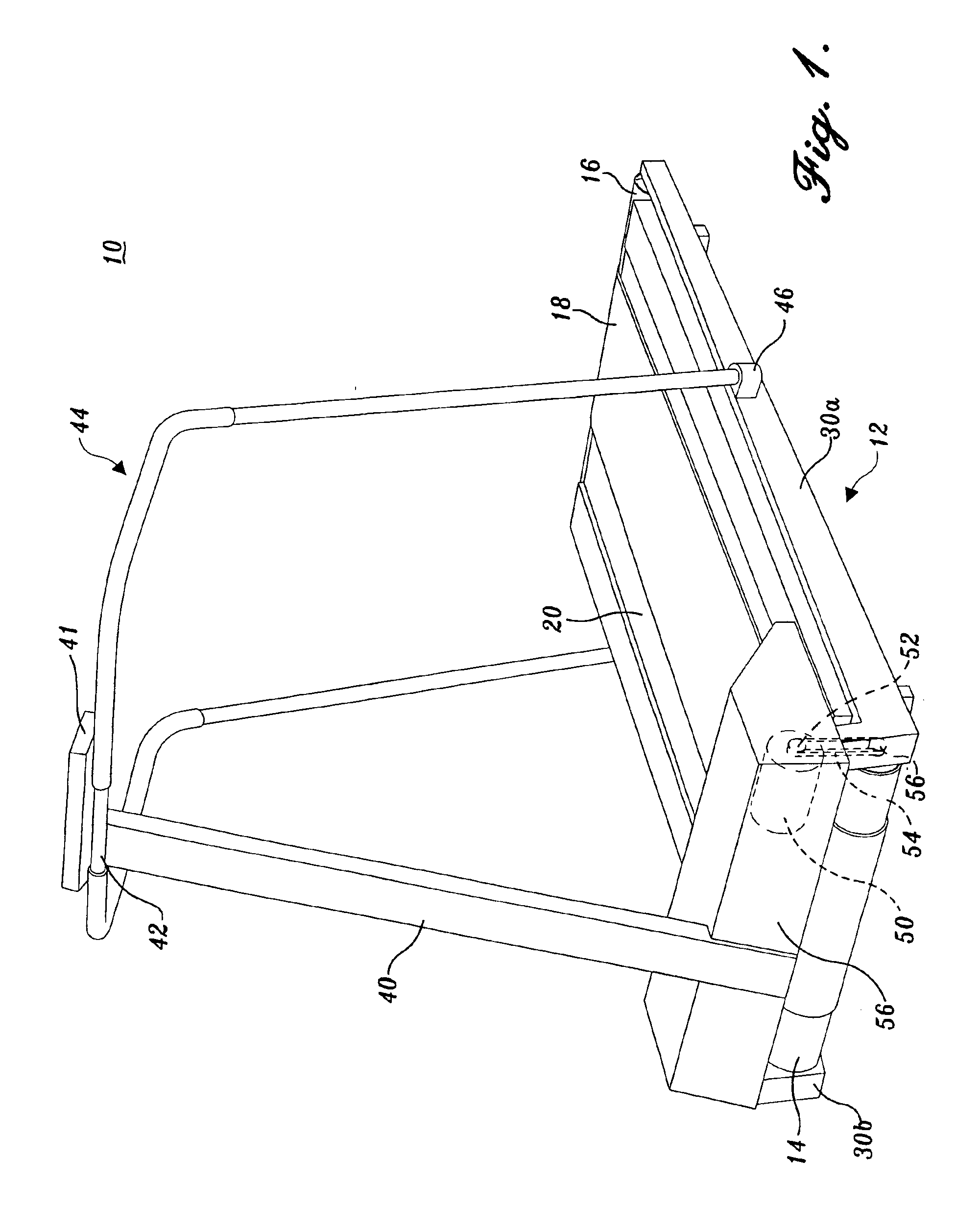
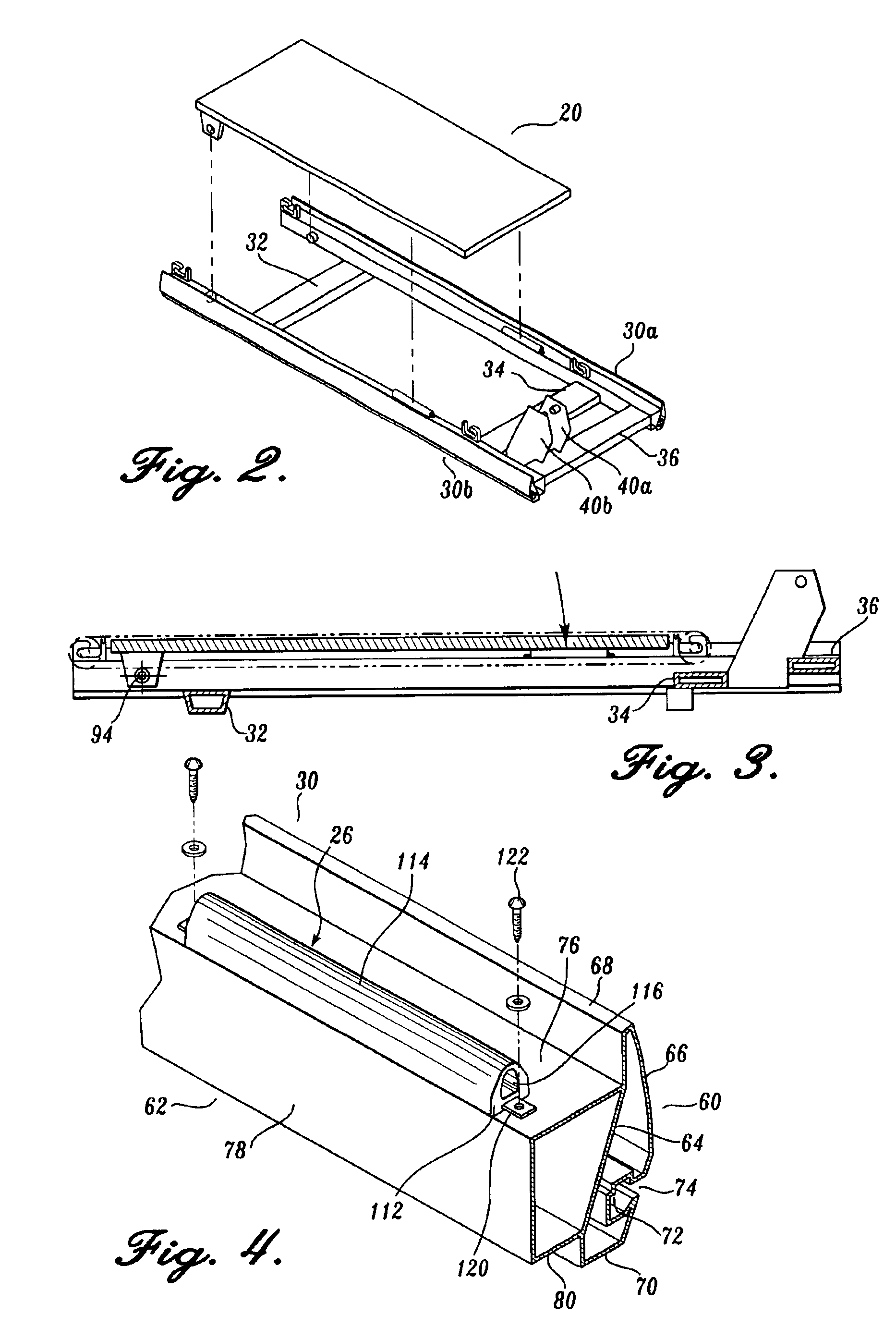
[0026]Initially referring to FIG. 1, a treadmill 10 constructed in accordance with the present invention includes a frame 12 on which is mounted a forward roller assembly 14 and a rearward roller assembly 16 are transversely mounted to the frame. For purposes of the present application, including the claims therein, the designation “forward end” refers to the direction in which the exerciser faces when using the treadmill. The terms “rear” and “forward” refer to opposite directions. An endless belt 18 is trained about the forward and rearward roller assemblies 14 and 16. A deck 20 is positioned between the upper run of the belt 18 and the frame 12. Referring additionally to FIGS. 2, 3 and 5, the rearward portion of the deck 20 is pivotally mounted to the frame by a pivot connection 24 to allow the rearward portion of the deck to pivot transversely to the frame about an axis extending relative to the length of the deck. Elongate, deformable springs 26 are mounted on the frame to unde...


PUM


Abstract

A treadmill (10) includes a frame on which are mounted transverse forward and rearward roller assemblies (14, 16). An endless belt (18) is trained about the forward and rearward roller assemblies. A deck (20) is positioned between the upper run of the belt and the frame. The rearward portion of the deck (20) is mounted to the frame by a pivot connection (24) to allow pivoting of the deck about an axis transversely to the length of the deck. Elongate springs (26) of adjustable stiffness are mounted either along the sides of the frame to underlie the side margins of the deck, or transversely of the deck, to support the deck in conjunction with the pivot connection (24) and to absorb impact loads imparted on the deck by the user.

Description

CROSS-REFERENCE TO RELATED APPLICATIONS[0001]This application is a divisional of application Ser. No. 09 / 481,059, filed Jan. 11, 2000 U.S. Pat. No. 6,572,513, which is a divisional of application Ser. No. 08 / 825,513, filed Mar. 31, 1997, now U.S. Pat. No. 6,013,011, priority from the filing date of which is hereby claimed under 35 U.S.C. § 120.FIELD OF THE INVENTION[0002]The present invention relates to exercise equipment, and more particularly to exercise treadmills, and still more particularly to suspension systems for supporting the deck of the exercise treadmill above an underlying frame structure.BACKGROUND OF THE INVENTION[0003]Exercise treadmills are widely used in spas, exercise clubs and also in individual residences to enable users to walk, jog or run indoors. This is especially useful during inclement weather and also at night or at other times when exercisers do not desire to run outdoors. Most exercise treadmills include first and second roller assemblies that are trans...

Claims


Application Information

Patent Timeline
IPC IPC(8): A63B22/00A63B22/02
CPCA63B22/02A63B22/0235A63B2022/0214A63B2022/0228A63B2225/30A63B22/0214A63B22/0228
Inventor MOORE, STEVEMORAN, THOMAS
Owner PRECOR
Learn More