Heat treatment method for cam piece

a treatment method and cam piece technology, applied in heat treatment equipment, valve drives, furnaces, etc., can solve the problems of difficult machined inner circumferential surfaces of cam pieces, difficult to machine, and excessive heat of the nose portion, so as to reduce heat transfer from the nose portion, reduce the effect of heat transfer and greater wall thickness

Active Publication Date: 2017-09-21
TOYOTA JIDOSHA KK
View PDF1 Cites 0 Cited by
  • Summary
  • Abstract
  • Description
  • Claims
  • Application Information

AI Technical Summary

Benefits of technology

[0012]In the above aspect, in the second step, the jig is inserted into the cam piece such that the nose portion faces the cutout of the jig. At a part where the inner circumferential surface of the cam piece is out of contact with the jig, heat transfer from the cam piece to the jig is difficult to be generated. Hence, the high-frequency induction heating is carried out in a state in which the inner circumferential surface in the nose portion is out of contact with the jig, thereby suppressing heat transfer from the nose portion to the jig more than heat transfer from the base portion to the jig. This means that quantity of heat per unit area that is transferred from the base portion becomes greater than quantity of heat per unit area that is transferred from the nose portion. Accordingly, in the second step, it is possible to carry out the high-frequency induction heating so as to increase the temperature of the nose portion having a greater wall thickness while suppressing increase in temperature of the base portion having a smaller wall thickness. Therefore, even if heat is applied to the cam piece such that quenching is carried out to a necessary depth in the nose portion, it is possible to suppress excessive heating of the base portion. This means that it is possible to appropriately control the quenching depth of the cam piece.

Problems solved by technology

In the case of quenching such a cam piece, the base portion having a smaller wall thickness might be excessively heated compared with the nose portion having a greater wall thickness even if heat is uniformly applied to a surface of the cam piece.
Specifically, since the nose portion having a greater wall thickness has a greater heat capacity than that of the base portion having a smaller wall thickness, a temperature of the nose portion is more difficult to be increased than a temperature of the base portion even if heat is uniformly applied to the surface of the cam piece.
If such variation in hardness occurs in the inner circumferential surface of the cam piece, it becomes difficult to machine the inner circumferential surface of the cam piece.
When such heat transfer is generated, if the temperature of the jig becomes increased and a difference in temperature between the cam piece and the jig becomes smaller, the heat becomes difficult to be transferred from the cam piece to the jig.

Method used


Image

  • Heat treatment method for cam piece
  • Heat treatment method for cam piece
  • Heat treatment method for cam piece

Examples


first embodiment

[0030]Hereinafter, a heat treatment method for a cam piece will be described with reference to FIG. 1 to FIG. 6.

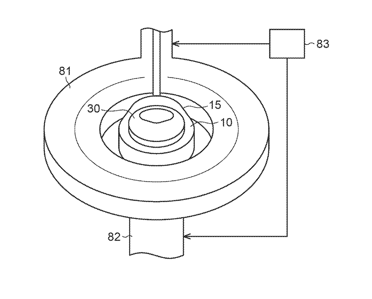
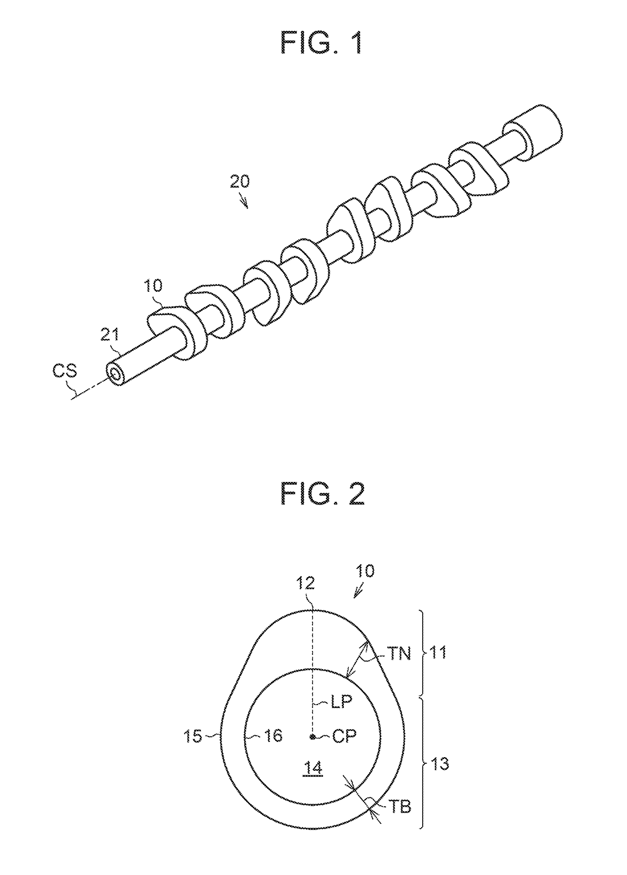
[0031]With reference to FIG. 1 and FIG. 2, a cam piece 10 targeted for a heat treatment will be described, hereinafter. As viewed in FIG. 1, each cam piece 10 configures a cam ridge to push and move a driving target in an assembly-type cam shaft 20. Each cam piece 10 is formed by forging steel or the like. The shaft 21 is inserted into the cam pieces 10. In FIG. 1, an axial line CS indicates a central axis of the shaft 21.

[0032]As shown in FIG. 2, the cam piece 10 includes a nose portion 11 configuring a cam ridge, and a base portion 13 configuring a base circle that does not act on motion of the driving target. The cam piece 10 is provided with an insertion hole 14 into which the shaft 21 of the cam shaft 20 is inserted. The insertion hole 14 has a diameter corresponding to a diameter of the shaft 21 so that the cam piece 10 can be shrinkage-fitted to the shaft 21. Subseq...

second embodiment

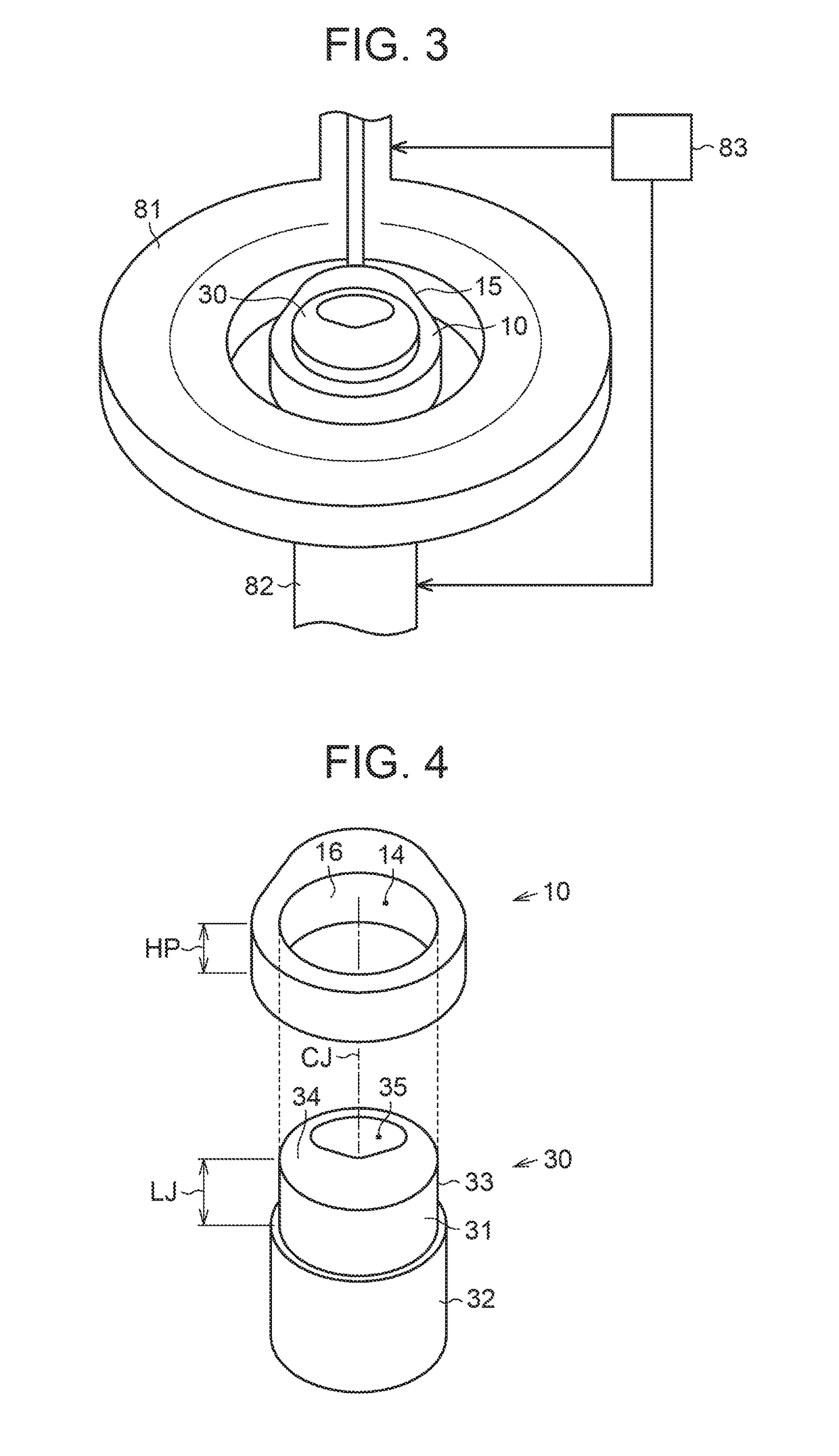
[0065]Next, operation and effect of the heat treatment method for the cam piece will be described, hereinafter. In heating step S2, the heating is carried out in a state in which the jig 50 having the cutout 57 is inserted in the cam piece 10 in such a manner that the nose portion 11 faces the cutout 57 of the jig 50. Hence, when the heating is carried out, at a part where the inner circumferential surface 16 in the base portion 13 and the outer circumferential surface 53 of the insertion portion 51 in the jig 50 are in contact with each other, heat transfer from the cam piece 10 to the jig 50 occurs. Meanwhile, heat transfer from the cam piece 10 to the jig 50 is unlikely to occur at a part where the inner circumferential surface 16 in the nose portion 11 and the outer circumferential surface 53 of the insertion portion 51 in the jig 50 are out of contact with each other, that is, at a part where the cutout 57 faces the inner circumferential surface 16. Hence, it is possible to su...


PUM

PropertyMeasurementUnit
central angleaaaaaaaaaa
“β”aaaaaaaaaa
thicknessaaaaaaaaaa

Abstract

Provided is a heat treatment method for a cam piece, and the cam piece has an insertion hole into which a cam shaft is inserted, a base portion configuring a base circle of a cam, and a nose portion configuring a cam ridge. The heat treatment method for the cam piece includes: a first step of using a jig formed into a shape having a cavity, the jig being inserted into the insertion hole such that the cavity is located between an inner circumferential surface of the nose portion of the cam piece and a central axis of the jig; and a second step of heating the cam piece from an outer circumferential surface side by high-frequency induction heating in a state in which the jig is inserted in the insertion hole of the cam piece.

Description

INCORPORATION BY REFERENCE[0001]The disclosure of Japanese Patent Application No. 2016-055790 filed on Mar. 18, 2016 including the specification, drawings and abstract is incorporated herein by reference in its entirety.BACKGROUND[0002]1. Technical Field[0003]The present disclosure relates to a heat treatment method for a cam piece configuring an assembly-type cam shaft.[0004]2. Description of Related Art[0005]As disclosed in Japanese Patent Application Publication No. 2002-356719, there has been known a quenching method of a cam shaft for the purpose of promoting enhancement of abrasion resistance of the cam shaft, or the like. In such a quenching method, subsequent to a heating step of heating the cam shaft, a cooling step of cooling the cam shaft is carried out so as to harden a structure of a heated portion of the cam shaft. As heat is applied more deeply by heating, a quenching depth that is a thickness of a hardened layer becomes deeper. Hence, in the quenching method disclose...

Claims


Application Information

Patent Timeline
Patent Type & Authority Applications(United States)
IPC IPC(8): H05B6/10F01L1/047F01L1/04
CPCH05B6/101F01L1/042F01L2103/00F01L2001/0471F01L1/047C21D1/10C21D1/18C21D9/30F01L2301/00F01L2303/00H05B6/102
Inventor TATEISHI, HIROKI
Owner TOYOTA JIDOSHA KK
Why Eureka
Try Eureka