Puncture Repair Liquid-Holding Container

a liquid-holding container and puncture technology, applied in the direction of flexible containers, packaging, tyres, etc., can solve the problems of improving the squeezability of the container, and achieve the effect of convenient grasping, efficient injection into the tire, and efficient delivery

Active Publication Date: 2016-11-03
THE YOKOHAMA RUBBER CO LTD
View PDF7 Cites 0 Cited by
  • Summary
  • Abstract
  • Description
  • Claims
  • Application Information

AI Technical Summary

Benefits of technology

[0007]Because the present technology is provided with the small-circumference section having a relatively small circumference on the bottom side away from the opening, as described above, the puncture repair liquid within the container migrates to the large-circumference section on the opening side having the relatively large circumference when the container is inverted to inject the puncture repair liquid, while air migrates toward the bottom side of the container, forming a space in which the puncture repair liquid is not present in the small-circumference section. The height of this space in the small-circumference section, which has a smaller cross-sectional area than the large-circumference section by virtue of its small circumference, is greater than in a conventional container of unvarying circumference, forcing more of the puncture repair liquid within the container toward the opening than would be if a conventional container were used. As a result, the puncture repair liquid can be more efficiently injected into the tire. In addition, the liquid surface of the puncture repair liquid is present in the small-circumference section at the beginning of the tire repair process, allowing the area near the liquid surface to be compressed by squeezing the small-circumference section, and allowing the puncture repair liquid to be more efficiently delivered. Moreover, the small circumference of the small-circumference section allows the section to be easily grasped by hand, enabling a user to easily squeeze the container. In this way, the small-circumference section facilitates squeezing and injection of the puncture repair liquid, thereby eliminating the need for improving squeezability by reducing the thickness of the outer wall of the puncture repair liquid-holding container to make the container itself more flexible. It is thus possible to ensure sufficient outer wall thickness, prevent degradation of the puncture repair liquid, and maintain the shape retention of the container.
[0008]In the present technology, it is preferable that the bottom of the container body have a convex shape that protrudes toward the outside of the container. Imparting such a shape allows the container to easily deform when squeezed, which is advantageous for improving squeezability.
[0009]In the present technology, it is preferable that a line indicating one-half the volume of the container body when the container is upright be positioned within a range from 60% to 80% of the cross-sectional height of the container body. This yields a satisfactory balance between the large-circumference section and the small-circumference section, which is advantageous for striking a balance between improving squeezability and preventing degradation of the puncture repair liquid.
[0010]In the present technology, it is preferable that the small-circumference section have a wall thickness greater than that of the large-circumference section. This improves the shape retention of the squeezed section, facilitating repeated squeezing.
[0011]In the present technology, it is preferable that the outer wall of the container body have a multilayered structure including at least three layers, an intermediate layer of the multilayered structure being made of a gas barrier resin. This allows degradation of the puncture repair liquid to be effectively prevented.

Problems solved by technology

This results in the difficult problem of improving the squeezability of the container while maintaining the shape retention and puncture repair liquid degradation preventing capability thereof.

Method used


Image

  • Puncture Repair Liquid-Holding Container
  • Puncture Repair Liquid-Holding Container
  • Puncture Repair Liquid-Holding Container

Examples


examples

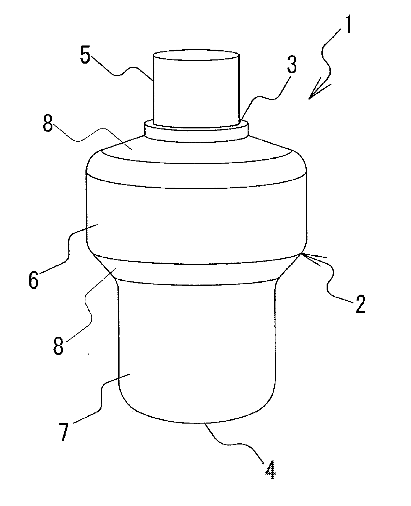
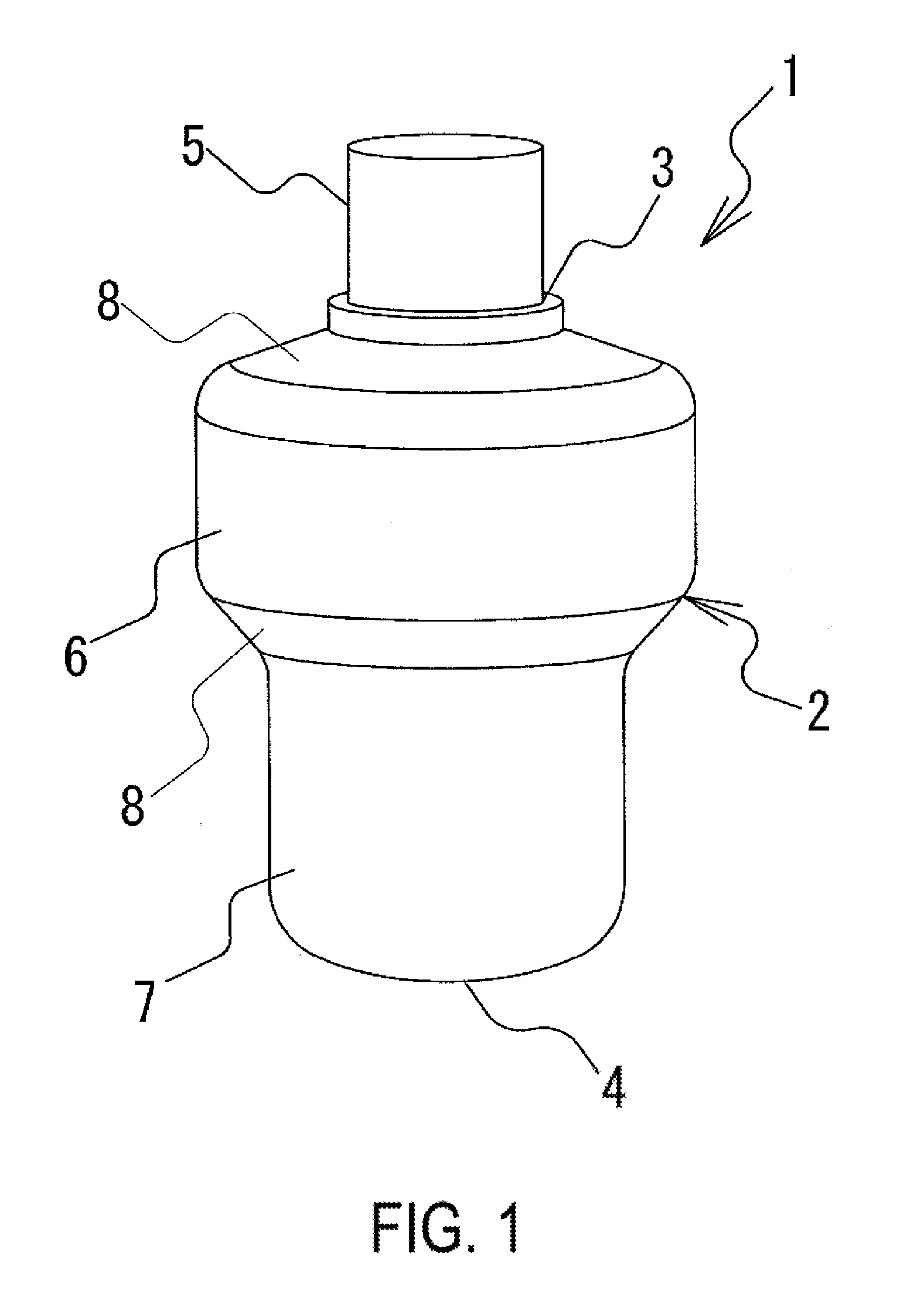
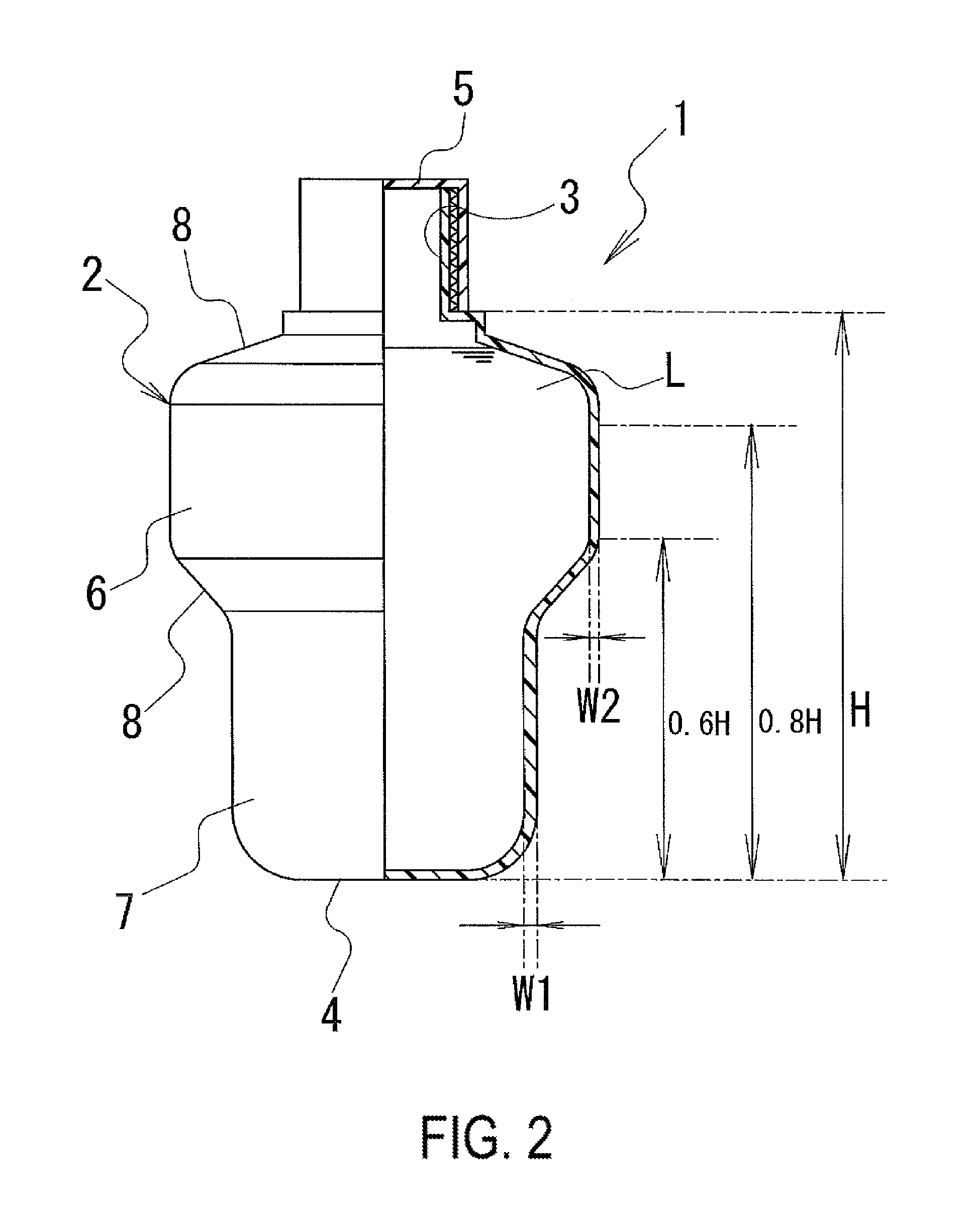
[0042]Puncture repair liquid-holding containers according to a Conventional Example 1 and Working Examples 1 to 6 all having a volume of 350 mL and having different dimensions with respect to the presence / absence of large- and small-circumference sections, frontal shape, the ratio of the circumference of the small-circumference section to the circumference of the large-circumference section, the shape of the bottom, the height of the half-volume line, the wall thickness of the large-circumference section, and the wall thickness of the small-circumference section as shown in Table 1 were prepared.

[0043]In all of the examples, the outer wall of the container body had a three-layered structure made of a synthetic resin, and the intermediate layer thereof was made of an ethylene / vinyl alcohol resin.

[0044]Puncture repair liquid injection time was measured for these experimental examples according to the method described hereafter; results are shown in Table 1.

[0045]Puncture Repair Liquid...


PUM

PropertyMeasurementUnit
thickness W1aaaaaaaaaa
thicknessaaaaaaaaaa
volumeaaaaaaaaaa

Abstract

Provided is a puncture repair liquid-holding container that allows for improved squeezability while suppressing puncture repair liquid degradation. In a puncture repair liquid-holding container in which puncture repair liquid is contained within a container body, the container body being squeezed during use to dispense the puncture repair liquid from an opening, the container body includes a large-circumference section and a small-circumference section, the large-circumference section being disposed on a side of the container body on which the opening is present, and the small-circumference section being disposed on a side of the container body on which a bottom is present.

Description

TECHNICAL FIELD[0001]The present technology relates to puncture repair liquid-holding containers, and, more specifically, to a puncture repair liquid-holding container that suppresses puncture repair liquid degradation and allows for improved squeezability while maintaining the shape retention of the container.BACKGROUND ART[0002]In recent years, when a tire mounted to a vehicle is punctured, puncture repair liquid is injected into the tire via the tire valve to temporarily repair the puncture, and the tire is filled with air. Installing a puncture repair device of this sort in a vehicle eliminates the need for carrying a spare tire in the vehicle, thereby conserving resources and reducing vehicle weight. This arrangement also yields the advantage that a space provided in the vehicle for carrying the spare tire can be used for other purposes.[0003]One example of a device for injecting puncture repair liquid is a hand-squeezable tire repair kit constituted by puncture repair liquid c...

Claims


Application Information

Patent Timeline
Patent Type & Authority Applications(United States)
IPC IPC(8): B29C73/16B65D1/32B29D30/06
CPCB29C73/166B65D1/32B29D30/0685B29C73/02B65D1/0223B65D35/08
Inventor SEKIGUCHI, TAKUMI
Owner THE YOKOHAMA RUBBER CO LTD
Why Eureka
Try Eureka