Textile part

Pending Publication Date: 2021-04-29
MEDI GMBH & CO KG
View PDF2 Cites 0 Cited by
  • Summary
  • Abstract
  • Description
  • Claims
  • Application Information

AI Technical Summary

Benefits of technology

[0014]The fastening element per se can be either flexible or rigid. “Flexible” is understood to be a corresponding flexibility of the fastening element, this enabling that the fastening element can fundamentally follow corresponding movements of the main panel, or corresponding variations in the geometry of the main panel, respectively, to a sufficient extent, thus for example when the main panel adapts to a region of a body located below said main panel, such as a lower leg or similar, and said fastening element can readily conjointly perform said adaption. The fastening element is thus far more flexible than the functional element, in this instance in the form of a stabilizing stiffener or the like, for example. The fastening element in such a case can be of a film-type, so to speak, having a corresponding wall thickness of, for example, 0.5 mm to 1.5 mm, wherein correspondingly greater wall thicknesses can be provided in the region of the corresponding form-fit geometries, for example, so as to guarantee a corresponding mounting of the form-fit. This can also be a textile carrier which has a plastics-material coating and which is likewise very flexible. In contrast, “rigid” is understood to be a mechanical property of the fastening element which is at least very similar or close to the mechanical properties of the functional element. This means that the fastening element per se has a sufficient stiffness and in itself already sufficiently stiffens the main panel, the latter preferably being a textile knitted panel, as described. Here too, the fastening element can be from plastics material, but in this instance either has a correspondingly greater thickness, for example in the range from 1.5 mm to 2.5 mm, or is made from a correspondingly stiff, or less flexible, respectively, plastics material. This means that a therapeutic purpose which is to be met by the textile part or the functional element, respe

Problems solved by technology

The functional element per se in this design embodiment is not connected to the main panel but connected to the latter merely by way of the carrier element, this leading to potential deficiencies arising in the functionality of the functional element since the properties of the latter, for example stabilizing properties, are not transmit

Method used


Image

  • Textile part
  • Textile part
  • Textile part

Examples


Embodiment Construction

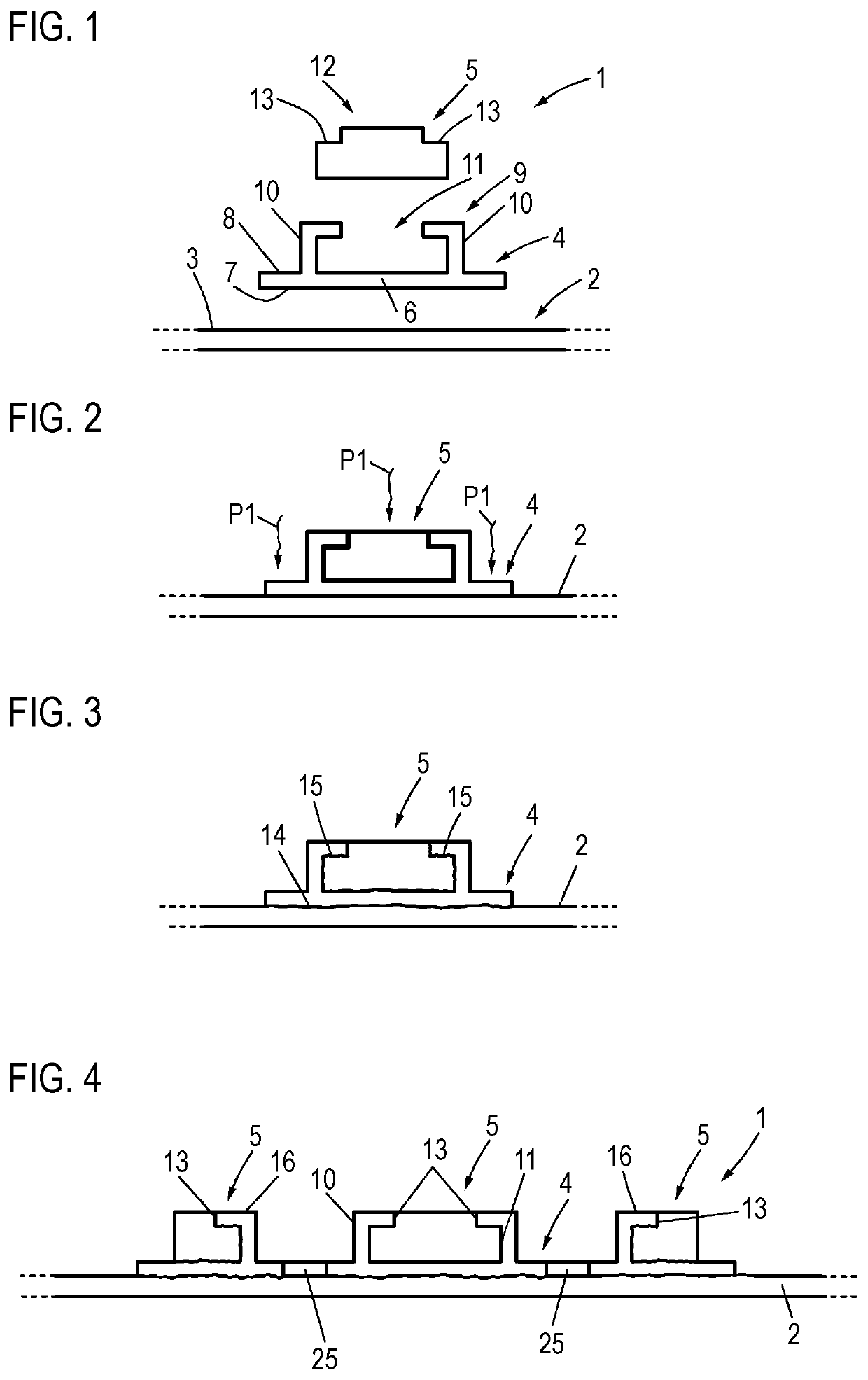
[0043]FIG. 1 in the form of an exploded view shows a textile part 1 according to the invention, comprising a main panel 2, preferably a textile knitted panel, in particular having compressive properties. The main panel 2 has an external side 3 onto which a fastening element 4 as well as a functional element 5, which is fixed to the fastening element 4, are subsequently placed. Alternatively to the disposal on the external side 3, there is of course also the possibility of placing the functional element 5 and the fastening element 4 on the opposite internal side of the main panel 2.

[0044]The fastening element 2 presently is a plastics-material element, for example, in the manner of an elongate, comparatively flexible or rather comparatively stiff plastics-material film, for example, which has a corresponding element base 6 having a lower side 7, wherein a form-fit contour 9 is configured on the opposite upper side 8 in the example shown, said form-fit contour 9 comprising two legs 10...


PUM

PropertyMeasurementUnit
Fractionaaaaaaaaaa
Flexibilityaaaaaaaaaa
Energyaaaaaaaaaa

Abstract

A textile part, in particular a textile orthopedic aid, including a textile main panel as well as at least one functional element from plastics material which is disposed on the main panel, wherein the functional element is connected either in a form-fitting or a form-fitting and materially integral manner to at least one fastening element, and the fastening element is connected in a materially integral manner to the main panel.

Description

CROSS-REFERENCE TO RELATED APPLICATIONS[0001]The present application claims priority of EP 19 204 990.6, filed Oct. 24, 2019, the priority of this application is hereby claimed and this application is incorporated herein by reference.BACKGROUND OF THE INVENTION[0002]The invention relates to a textile part, in particular a textile orthopedic aid, comprising a textile main panel as well as at least one functional element from plastics material which is disposed on the main panel.[0003]Such a textile part, as is known from EP 2 779 963 B1, for example, is embodied as a sleeve or as a bandage and serves for bearing on the body of a wearer. The textile part has a textile main panel on which at least one functional element from plastics material is disposed, said functional element being embodied as, for example, an elongate splint or as a joint or similar. This functional element serves for imparting to the textile part a specific functional property which is helpful to the wearer, thus ...

Claims


Application Information

Patent Timeline
IPC IPC(8): A61L15/22A61F5/01A61F13/08
CPCA61L15/22A61L2300/608A61F13/08A61F5/01A61F13/061A61F5/0109A61F5/0123
Inventor BAUER, PATRICK
Owner MEDI GMBH & CO KG
Why Eureka
Try Eureka