State controller apparatus

a state controller and apparatus technology, applied in the direction of computer control, process and machine control, instruments, etc., can solve the problems of limiting the period of activation restricting the power consumption of the end effecting device, so as to prevent the activation period and restrain the momentary upsurge of power consumption

Inactive Publication Date: 2005-09-20
YAMATAKE HONEYWELL CO LTD
View PDF11 Cites 9 Cited by
  • Summary
  • Abstract
  • Description
  • Claims
  • Application Information

AI Technical Summary

Benefits of technology

[0015]In the state control apparatus, the parameter generator may generate a prioritization parameter indicating a prioritization among the end effecting devices in each group. The comprehensive controller may adjust respective activations of the end effecting devices in each group on the basis of parameters including the prioritization parameter. With such a structure, a plurality of specific end effecting devices may be activated for longer periods preferentially. In addition, it is possible to cause the plurality of specific end effecting devices to enter a desirable state quickly. It is also possible to maintain the desirable state precisely for the plurality of specific end effecting device in comparison with the other end effecting devices.
[0016]In the state control apparatus, the comprehensive controller may differentiate an activating start moment of an end effecting device belonging to a group from that of another end effecting device belonging to another group. With such a structure, it is possible to prevent a plurality of end effecting devices belonging to different groups from starting to activate simultaneously although parallel processing is conducted by the “grouping.” Therefore, a momentary upsurge of power consumption may be restrained.
[0017]In the state control apparatus, the comprehensive controller may delay a start moment of outputting the activating signal for an end effecting device. With such a structure, although the end effecting devices are activated and deactivated by relays or switches that may involve delays caused by mechanical motions, it is possible to prevent the activation periods of the end effecting devices from overlapping one another.

Problems solved by technology

Furthermore, since activating signals for a plurality of end effecting devices are not output simultaneously, the end effecting devices may be activated under restricted power consumption.
With such a structure, the periods for activating the end effecting devices may be limited appropriately in accordance with application, environment, property, and other factors.

Method used


Image

  • State controller apparatus
  • State controller apparatus
  • State controller apparatus

Examples


Embodiment Construction

[0042]In the following, with reference to accompanying drawings, a best mode for carrying out the present invention will be described for exemplifying the present invention.

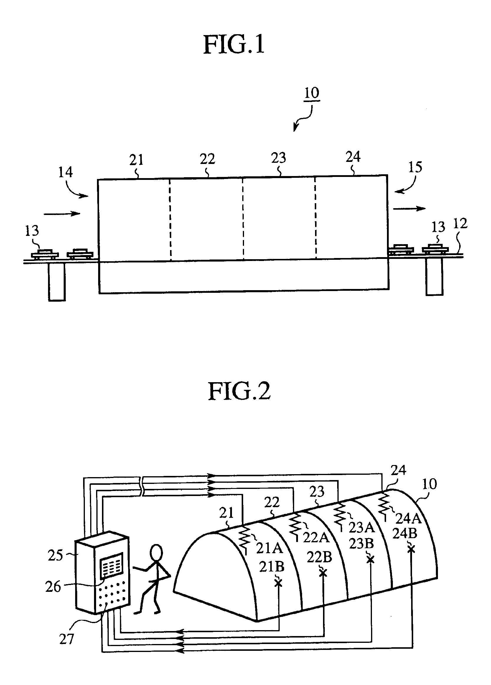
[0043]A state control apparatus according to an embodiment of the present invention may be applied to, for example, a furnace 10 in FIG. 1. The furnace 10 contains a cavity extending along its longitudinal direction, along which a conveyor 12 is arranged so as to pass through the cavity. Heated subjects 13 transferred by the conveyor 12 enters at the entrance 14 of the furnace 10 and leaves the furnace 10 by the exit 15 while the heated subjects 13 are heated during passing through the furnace 10. The furnace 10 may be generally divided into four heated zones 21, 22, 23, and 24.

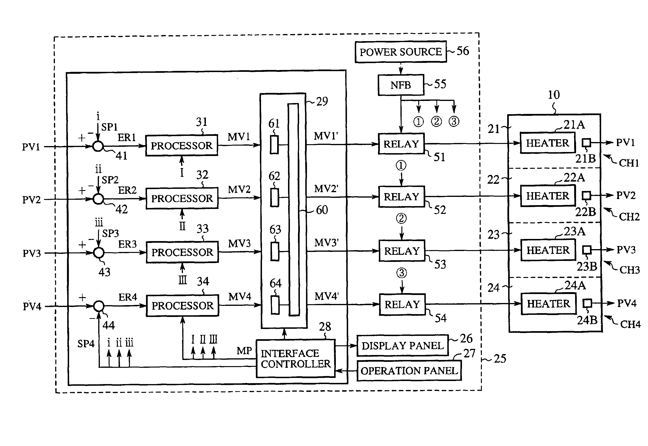
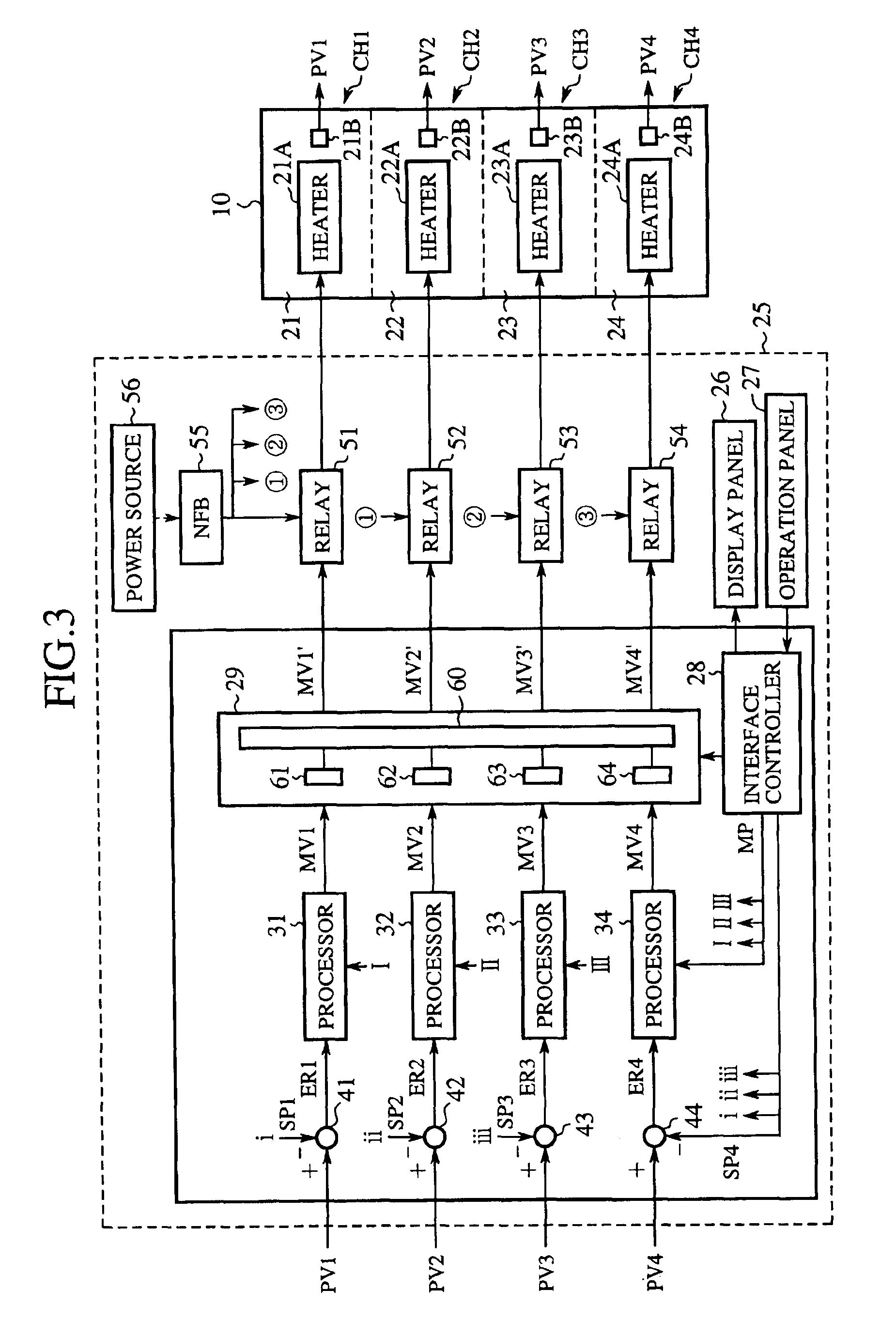
[0044]As shown in FIG. 2, electric heaters (end effecting devices) 21A, 22A, 23A, and 24A are situated within the heated zones 21, 22, 23, and 24 of the furnace 10, respectively. Electric (e.g. thermocouple-type) thermometers 21B, 22B, 23B...


PUM

PropertyMeasurementUnit
currentaaaaaaaaaa
currentaaaaaaaaaa
cycle-timeaaaaaaaaaa

Abstract

A state control apparatus includes a calculator for calculating adjustment amounts for adjusting a plurality of end effecting devices on the basis of preset values and measured amounts measured by a plurality of meters. The measured amounts indicate respective states of the end effecting devices. The adjustment amounts are required for conforming the measured amounts to the preset values, respectively. The state control apparatus further includes a parameter generator for generating a plurality of parameters on the basis of settings by a user. The state control apparatus further includes a comprehensive controller for outputting activating signals for activating the respective end effecting devices based on the respective adjustment amounts and the plurality of parameters. When the comprehensive controller outputs one of the activating signals for activating one of the end effecting devices, the comprehensive controller does not output the other activating signals for activating the other end effecting devices.

Description

CROSSREFERENCE TO RELATED APPLICATION[0001]This application is a 35 USC 371 National Phase Entry Application from PCT / JP00 / 08780, filed Dec. 12, 2000.TECHNICAL FIELD[0002]The present invention relates to a state control apparatus. More specifically, the present invention relates to a state control apparatus for activating a plurality of end effecting devices harmonically under restricted power consumption.BACKGROUND ART[0003]Generally, a plurality of independent control loops have been provided for managing states of a plurality of controlled subjects (end effecting devices), e.g., temperatures of heaters. Each control loop is provided with a controller, such as a PID (proportional integral differential) processor for controlling the corresponding end effecting device. In a system including a plurality of control loops, a plurality of end effecting devices may be frequently activated at the same period, thereby increasing power consumption temporarily. Therefore, high capabilities a...

Claims


Application Information

Patent Timeline
Patent Type & Authority Patents(United States)
IPC IPC(8): G05B15/02G05B23/02
CPCG05B15/02H05B1/023
Inventor HIRAYAMA, HIROFUMIKATO, HIROYUKI
Owner YAMATAKE HONEYWELL CO LTD
Why Eureka
Try Eureka