Electrophoretic dispersion, electrophoretic display device, method of manufacturing electrophoretic display device, and electronic system

a technology of electrophoretic display device and electrophoretic dispersion, which is applied in the direction of liquid/fluent solid measurement, fluid pressure measurement, peptide, etc., can solve the problems of reduced display visibility, viewer's eyes may suffer from the flicker of light source, and reflective display device is attracting much attention, so as to achieve superior display performance

Active Publication Date: 2005-09-20
E INK CORPORATION
View PDF23 Cites 131 Cited by
  • Summary
  • Abstract
  • Description
  • Claims
  • Application Information

AI Technical Summary

Benefits of technology

[0017]The invention provides an electrophoretic dispersion that reduces or prevents the aggregation among electrophoretic particles, an electrophoretic display device using the electrophoretic dispersion, a method of manufacturing the electrophoretic display device, and an electronic system superior in display performance.
[0047]Thus, an electronic system superior in display performance can be obtained.

Problems solved by technology

However, such liquid crystal display devices have a problem in that display visibility is reduced depending on the view angle or due to reflected light.
Also, a viewer's eyes may suffer from the flicker of light sources.
Therefore, numerous attempts are being made to develop display devices harmless to eyes.
Reflective display devices are attracting much attention because the units have low power consumption and are harmless to eyes.

Method used


Image

  • Electrophoretic dispersion, electrophoretic display device, method of manufacturing electrophoretic display device, and electronic system
  • Electrophoretic dispersion, electrophoretic display device, method of manufacturing electrophoretic display device, and electronic system
  • Electrophoretic dispersion, electrophoretic display device, method of manufacturing electrophoretic display device, and electronic system

Examples


first exemplary embodiment

[0064]A first exemplary embodiment of the electrophoretic display device of the invention will be described first.

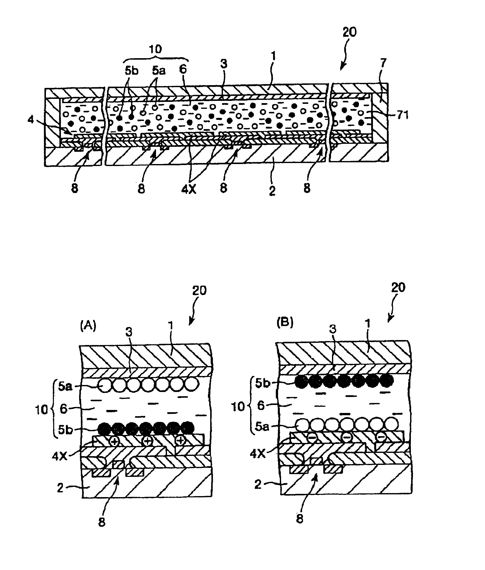
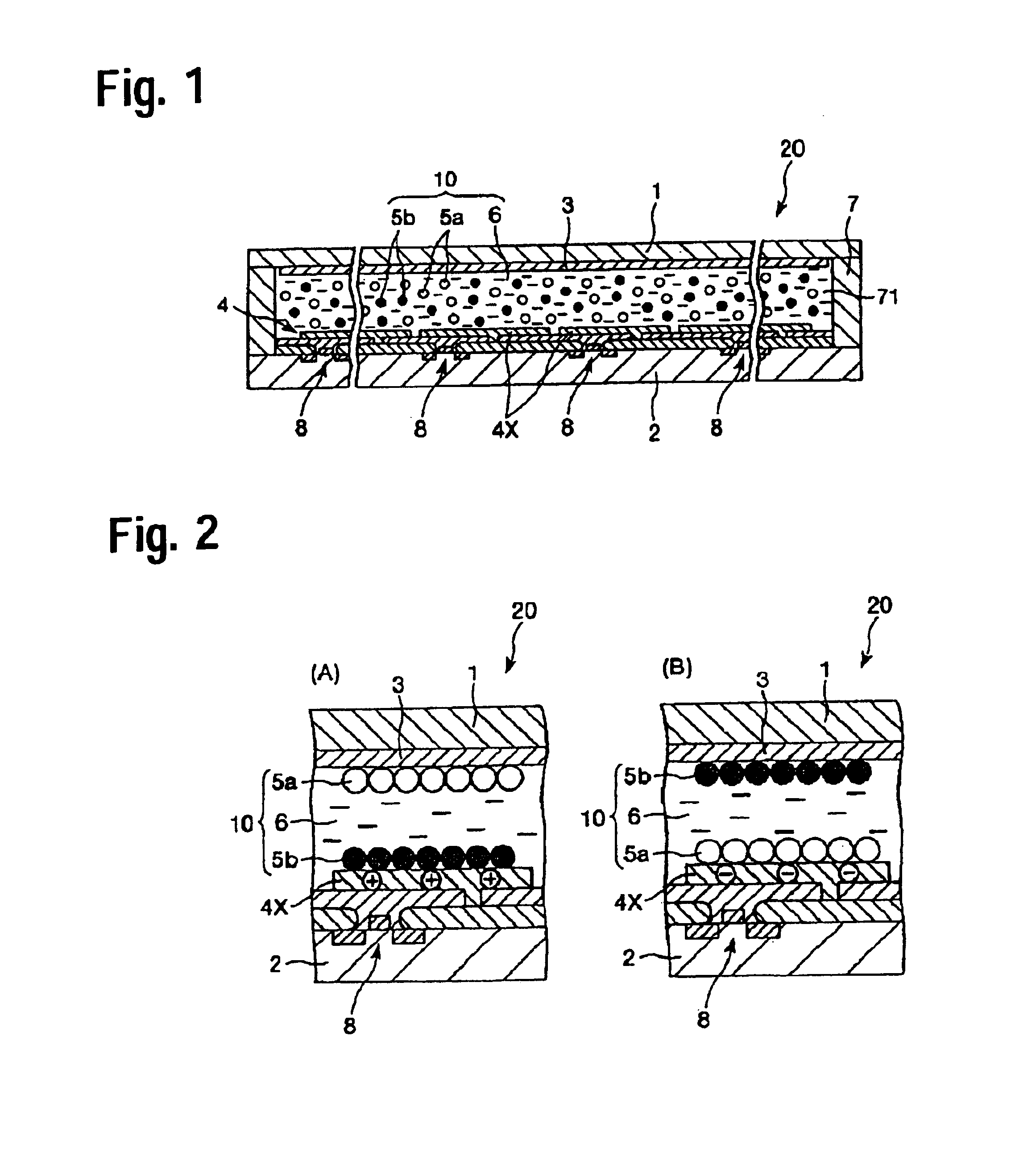
[0065]FIG. 1 is a longitudinal cross-sectional schematic showing the first exemplary embodiment of the electrophoretic display device of the invention. FIG. 2 is a schematic showing the working principle of the electrophoretic display device illustrated in FIG. 1.

[0066]For convenience of explanation, in the description to be presented below, the upper sides in the FIGS. 1 and 2 are expressed by “top” or “above” and the lower sides are expressed by “bottom” or “below.”

[0067]The electrophoretic display device (electrophoretic display unit) 20 illustrated in FIG. 1 has: a first substrate 1 with a first electrode 3; a second substrate 2 with a second electrode 4 facing the first electrode 3; and an electrophoretic dispersion 10 provided between the first substrate 1 and the second substrate 2. The portions thereof will be described below in turn.

[0068]The first substrate 1 a...

second exemplary embodiment

[0129]Now, a second exemplary embodiment of the electrophoretic display device of the invention will be described.

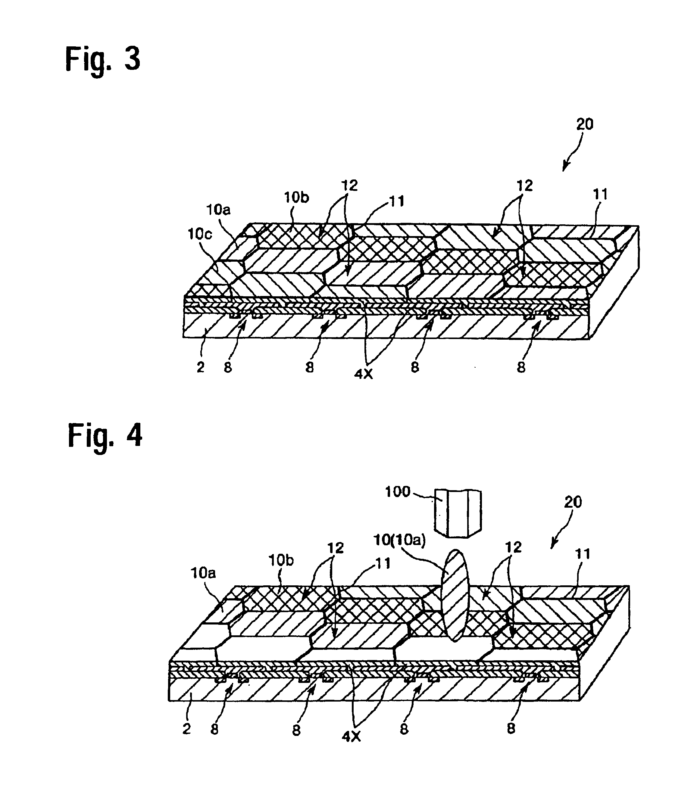
[0130]FIG. 3 is a schematic showing (or partially showing) the second exemplary embodiment of the electrophoretic display device of the invention. FIG. 4 is an illustration showing a step of a manufacturing process of the electrophoretic display device illustrated in FIG. 3. In FIG. 3, the first substrate and the first electrode are omitted.

[0131]The electrophoretic display device of the second exemplary embodiment will be described below with the focus on the differences from the first exemplary embodiment, and the descriptions of like matters are to be omitted.

[0132]The electrophoretic display device 20 of the second exemplary embodiment is identical to the electrophoretic display device 20 of the first exemplary embodiment except that the electrophoretic dispersion 10 is distributed and placed in given places.

[0133]As shown in FIG. 3, in the second exemplary embodimen...

third exemplary embodiment

[0148]Now, a third exemplary embodiment of the electrophoretic display device of the invention will be described.

[0149]FIG. 5 is a schematic showing (or partially showing) the third exemplary embodiment of the electrophoretic display device of the invention.

[0150]The electrophoretic display device of the third exemplary embodiment will be described below with the focus on the differences from the first and second exemplary embodiments, and the descriptions of like matters are to be omitted.

[0151]The electrophoretic display device 20 of the third exemplary embodiment is identical to the electrophoretic display device 20 of the second exemplary embodiment except for the layout pattern of the electrophoretic dispersion 10.

[0152]As shown in FIG. 5, in the electrophoretic display device 20 of the third exemplary embodiment, three cell spaces 12 adjacent to each other are respectively filled with a red electrophoretic dispersion 10a, a green electrophoretic dispersion 10b, and a blue elec...


PUM

PropertyMeasurementUnit
particle sizeaaaaaaaaaa
thicknessesaaaaaaaaaa

Abstract

To provide an electrophoretic dispersion capable of reducing or preventing the aggregation of electrophoretic particles, an electrophoretic display device using the electrophoretic dispersion, a method of manufacturing the electrophoretic display device, and an electronic system superior in display performance; an electrophoretic display device (electrophoretic display unit) has: a first substrate with a first electrode; a second substrate with a second electrode opposite the first electrode; and an electrophoretic dispersion provided between the first substrate and second substrate. The electrophoretic dispersion (dispersion for electrophoretic display units) includes a liquid phase insulative dispersion medium and electrophoretic particles dispersed in the dispersion medium, the particles electrophoretically migrated under an influence of an electric field. Also included as the electrophoretic particles, inorganic particles and resin particles dyed a color different from that of the inorganic particles and having an electrical polarity opposite to that of the inorganic particles.

Description

BACKGROUND OF THE INVENTION[0001]1. Field of Invention[0002]The present invention relates to an electrophoretic dispersion, an electrophoretic display device, a method of manufacturing an electrophoretic display device, and an electronic system.[0003]2. Description of Related Art[0004]In recent years, portable information systems have been intensively enhanced. Demand for thin display devices with low power consumption are particularly growing. Various attempts have been made to cope with such demands. Liquid crystal display devices (liquid crystal display units) have satisfied the demands until now.SUMMARY OF THE INVENTION[0005]However, such liquid crystal display devices have a problem in that display visibility is reduced depending on the view angle or due to reflected light. Also, a viewer's eyes may suffer from the flicker of light sources. Therefore, numerous attempts are being made to develop display devices harmless to eyes.[0006]Reflective display devices are attracting muc...

Claims


Application Information

Patent Timeline
Patent Type & Authority Patents(United States)
IPC IPC(8): G02F1/01G02F1/167
CPCG02F1/167
Inventor KANBE, SADAO
Owner E INK CORPORATION
Why Eureka
Try Eureka