Electrophoretic dispersion, electrophoretic display device, method of manufacturing electrophoretic display device, and electronic system

a technology of electrophoretic display device and electrophoretic dispersion, which is applied in the direction of optics, instruments, optical elements, etc., can solve the problems of reduced display visibility, high display performance of reflective display device, and viewer's eyes suffering from light source flicker, etc., to achieve superior display performance

Active Publication Date: 2005-02-03
E INK CORPORATION
View PDF9 Cites 25 Cited by
  • Summary
  • Abstract
  • Description
  • Claims
  • Application Information

AI Technical Summary

Benefits of technology

[0017] The invention provides an electrophoretic dispersion that reduces or prevents the aggregation among electrophoretic particles, an electrophoretic display device using the electrophoretic dispersion, a method of manufacturing the electrophoretic display device, and an electronic system superior in display performance.
[0047] Thus, an electronic system superior in display performance can be obtained.

Problems solved by technology

However, such liquid crystal display devices have a problem in that display visibility is reduced depending on the view angle or due to reflected light.
Also, a viewer's eyes may suffer from the flicker of light sources.
Therefore, numerous attempts are being made to develop display devices harmless to eyes.
Reflective display devices are attracting much attention because the units have low power consumption and are harmless to eyes.

Method used


Image

  • Electrophoretic dispersion, electrophoretic display device, method of manufacturing electrophoretic display device, and electronic system
  • Electrophoretic dispersion, electrophoretic display device, method of manufacturing electrophoretic display device, and electronic system
  • Electrophoretic dispersion, electrophoretic display device, method of manufacturing electrophoretic display device, and electronic system

Examples


example 1

[0251] 1. Preparation of the Electrophoretic Dispersion

[0252] A red electrophoretic dispersion was prepared by ultrasonically dispersing 8 g of acrylic particles colored red (“CHEMISNOW,” manufactured by Soken Chemical & Engineering Co., Ltd.) and 8 g of titania particles (“CR-90,” manufactured by Ishihara Sangyo Kaisha, Ltd.) in 80 ml of dodecylbenzene, the titania particles being processed with a surface-treating agent manufactured by Ajinomoto Co., Inc.

[0253] The acrylic particles having an average particle size of 4 μm and the titania particles having an average particle size of 0.2-0.3 μm were used here.

[0254] In the same way, a green electrophoretic dispersion and a blue electrophoretic dispersion were prepared.

[0255]“CHEMISNOW,” manufactured by Soken Chemical & Engineering Co., Ltd. were used for the acrylic particles colored green, and also “CHEMISNOW,” manufactured by Soken Chemical & Engineering Co., Ltd. were used for the acrylic particles colored blue.

[0256] 2. Manu...

example 2

[0264] The electrophoretic display device was manufactured by the same process as that of Example 1 except that the partitions were different in shape and electrophoretic dispersions of four colors were used.

[0265] 1. Preparation of the Electrophoretic Dispersion

[0266] In the same way as in Example 1, a red electrophoretic dispersion, green electrophoretic dispersion, blue electrophoretic dispersion, and black electrophoretic dispersion were prepared.

[0267] For the acrylic particles colored black, “CHEMISNOW” manufactured by Soken Chemical & Engineering Co., Ltd. was used.

[0268] 2. Manufacturing of the Electrophoretic Display Device

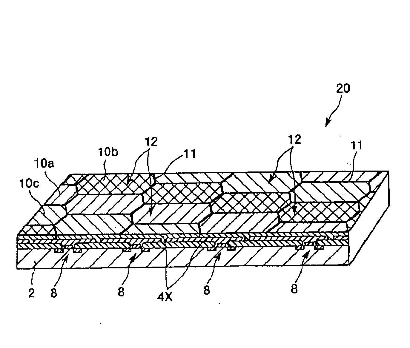
[0269] The partitions were shaped into a honeycomb form as illustrated in FIG. 6. Then the red, green, blue, and black electrophoretic dispersions were filled in cell spaces with the layout pattern illustrated in FIG. 6.

[0270] As a result, an electrophoretic display device superior in display in black to that in Example 1 could be obtained.

example 3

[0271] 1. Preparation of Microcapsules

[0272] Each electrophoretic dispersion, prepared in the same process as in Example 1, was added to 60 ml of an aqueous solution containing 4 g of gelatin and 4 g of acacia gum, and the mixture was agitated at 800 rpm and encapsulated into capsules.

[0273] Thereafter, the untreated capsules were processed in a pH-adjusting step using acetic acid, sodium carbonate, etc., a cross-linking step using formalin, a drying step, and the like in that order, whereby microcapsules corresponding to the individual colors were prepared respectively.

[0274] 2. Manufacturing of the Electrophoretic Display Device

[0275] First, a substrate having thin film transistor elements (TFT glass substrate) was obtained. The substrate was prepared by the same process as that for preparing TFT substrates used for manufacturing liquid crystal displays.

[0276] The microcapsules of each of the colors (which are the same as in Example 4) had an average particle size of 50-60 μm...


PUM

PropertyMeasurementUnit
particle sizeaaaaaaaaaa
thicknessesaaaaaaaaaa

Abstract

To provide an electrophoretic dispersion capable of reducing or preventing the aggregation of electrophoretic particles, an electrophoretic display device using the electrophoretic dispersion, a method of manufacturing the electrophoretic display device, and an electronic system superior in display performance; an electrophoretic display device (electrophoretic display unit) has: a first substrate with a first electrode; a second substrate with a second electrode opposite the first electrode; and an electrophoretic dispersion provided between the first substrate and second substrate. The electrophoretic dispersion (dispersion for electrophoretic display units) includes a liquid phase insulative dispersion medium and electrophoretic particles dispersed in the dispersion medium, the particles electrophoretically migrated under an influence of an electric field. Also included as the electrophoretic particles, inorganic particles and resin particles dyed a color different from that of the inorganic particles and having an electrical polarity opposite to that of the inorganic particles.

Description

BACKGROUND OF THE INVENTION [0001] 1. Field of Invention [0002] The present invention relates to an electrophoretic dispersion, an electrophoretic display device, a method of manufacturing an electrophoretic display device, and an electronic system. [0003] 2. Description of Related Art [0004] In recent years, portable information systems have been intensively enhanced. Demand for thin display devices with low power consumption are particularly growing. Various attempts have been made to cope with such demands. Liquid crystal display devices (liquid crystal display units) have satisfied the demands until now. SUMMARY OF THE INVENTION [0005] However, such liquid crystal display devices have a problem in that display visibility is reduced depending on the view angle or due to reflected light. Also, a viewer's eyes may suffer from the flicker of light sources. Therefore, numerous attempts are being made to develop display devices harmless to eyes. [0006] Reflective display devices are a...

Claims


Application Information

Patent Timeline
Patent Type & Authority Applications(United States)
IPC IPC(8): G02F1/167
CPCG02F1/167
Inventor KANBE, SADAO
Owner E INK CORPORATION
Why Eureka
Try Eureka