Local information-based restoration arrangement

a technology of local information and restoration arrangement, applied in data switching networks, frequency-division multiplexes, instruments, etc., can solve the problems of slow network connection, slow network connection, and cable cut, and achieve the effect of reducing the cost of repair and maintenance, improving service life, and improving service li

Inactive Publication Date: 2005-09-20
AMERICAN TELEPHONE & TELEGRAPH CO
View PDF19 Cites 177 Cited by
  • Summary
  • Abstract
  • Description
  • Claims
  • Application Information

AI Technical Summary

Benefits of technology

[0005]An advance in the art is achieved with an arrangement that employs the notion that a failure at any point in the network can be quickly remedied by rerouting traffic at the failed point though network elements in close topological proximity to the failed point. This is accomplished by algorithmically and distributively assigning the responsibility for recovery from all failures to different network nodes. In one illustrative embodiment, each failure is assigned to one primary command node, and to a secondary, backup, command node.

Problems solved by technology

Prior to the optical transport era, failed network connectivity due to a cable cut typically took four to six hours for manual repair.
Still, FASTAR has certain limitations rooted in its central control architecture.
For example, central collection of alarms creates a bottleneck at the central processor.
Also, the problem of planning restoration paths for many disparate routes is mathematically complex and quite difficult to solve, leading to restoration reroute solutions that are typically sub-optimal.
Since failure detection and protection switching are done automatically by the ADMs, restoration is typically fast and can routinely take less than 200 ms.

Method used


Image

  • Local information-based restoration arrangement
  • Local information-based restoration arrangement
  • Local information-based restoration arrangement

Examples


Embodiment Construction

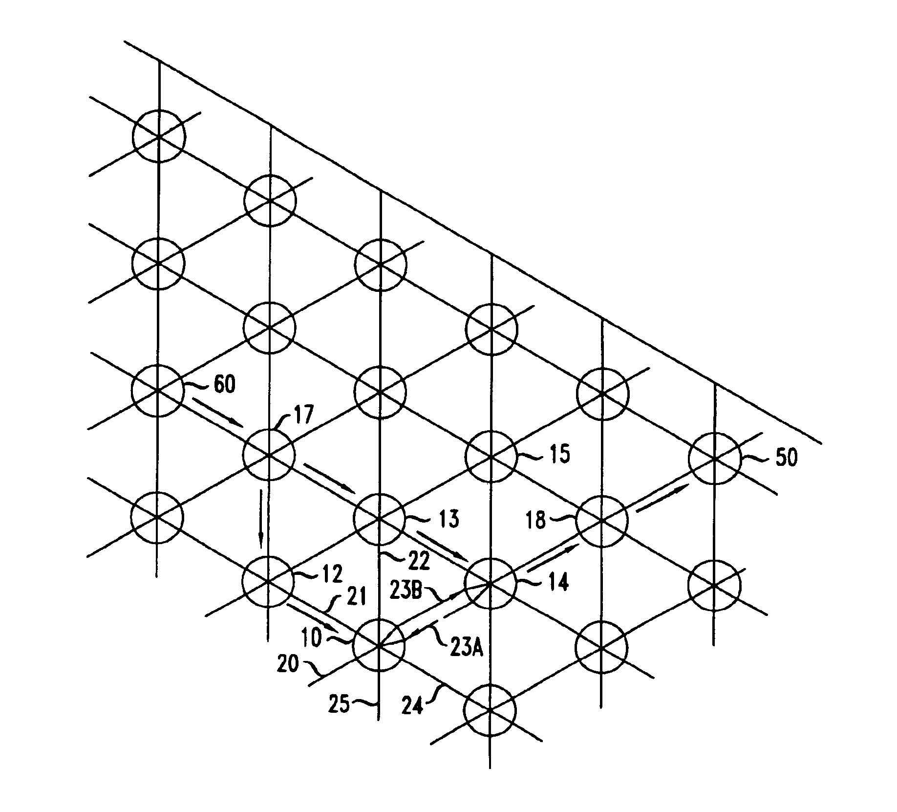
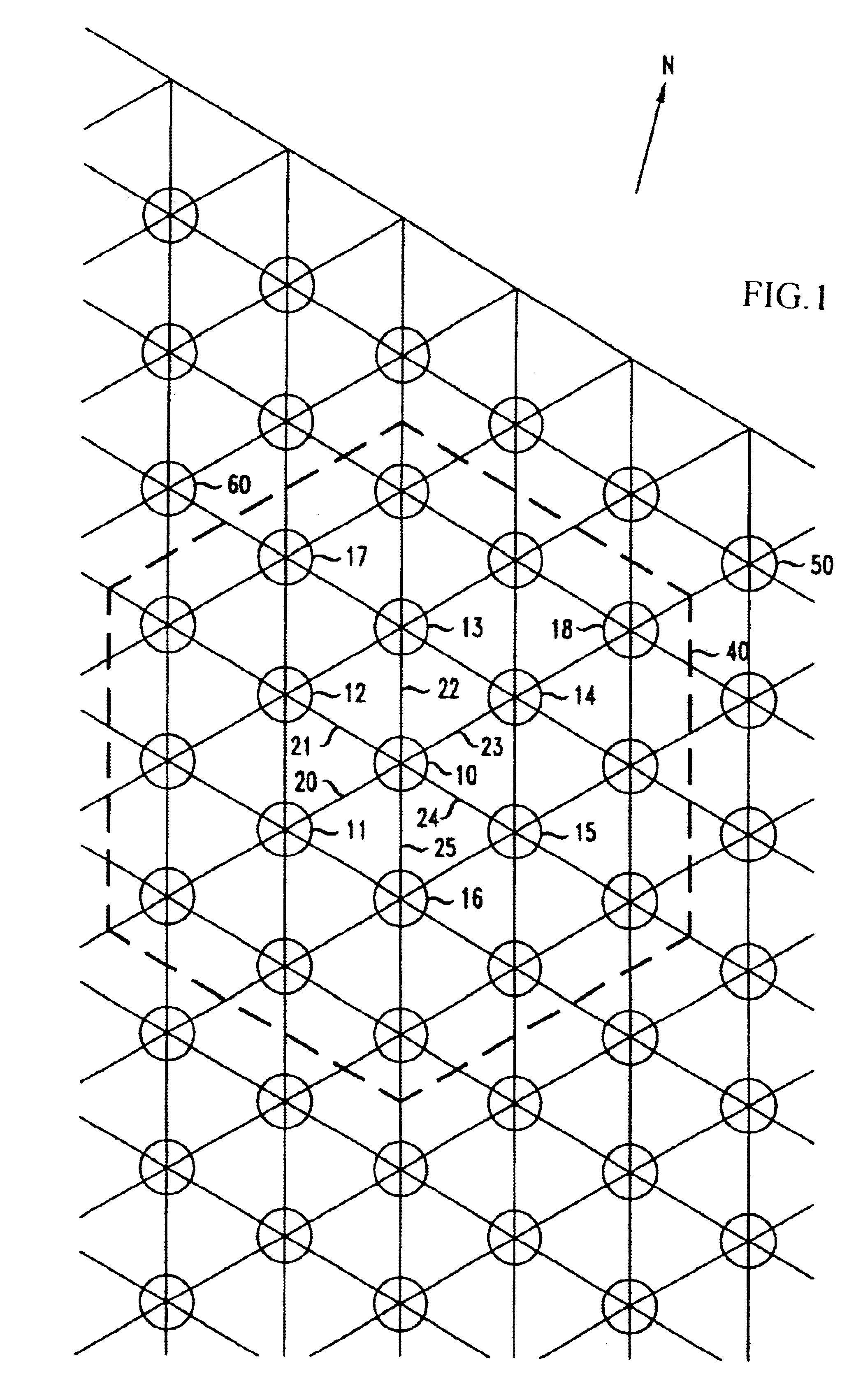
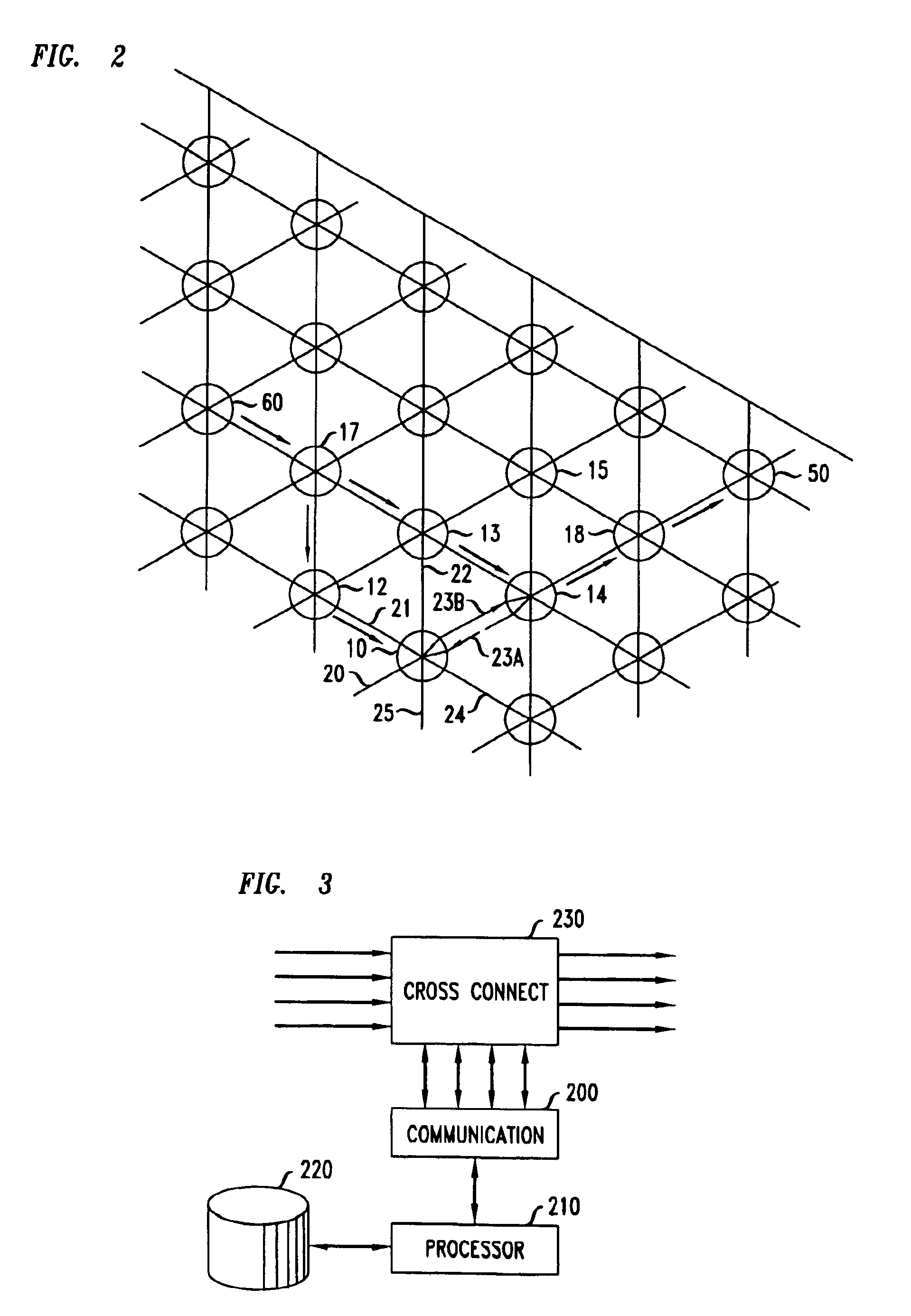
[0011]A distributed control system potentially is faster; more efficient and more robust than a central control system. Therefore the failure restoration management system disclosed herein centers on the use of a distributed restoration management of local failure. In accordance with the principles disclosed herein, the concept of a neighborhood is employed, based on the fact that the most efficient restoration routes are highly likely to pass through a small collection of nodes within close topological proximity to the failure site. FIG. 1 presents a view of a network in which the principles disclosed herein may be applied. For ease of understanding, the depicted network is of a very simple and regular topology (hexagonal) but, of course, that is not a requirement of this invention.

[0012]To better understand the description that follows, it is useful to review some of the nomenclature employed herein.

[0013]In the context of this disclosure, a path corresponds to the route over whic...


PUM


Abstract

A network that is architectured to distributively be responsible for remedying failures achieves advantageous operation. This is accomplished by algorithmically and distributively assigning the responsibility for recovery from all failures to different network nodes and by re-routing traffic at the failed point though network elements in close topological proximity to the failed point. Each node maintains an awareness of the spare resources in its neighborhood and pre-plans re-route plans for each of the failures for which it is responsible. It maintains the created re-route plans and, upon detection of a failure, transmits a re-route plan to particular nodes that participate in the re-routing recovery planned for such a failure. Alternatively, it transmits re-route plans to the nodes that need them, and upon detection of a failure, the network node broadcasts an ID of the re-route plan that needs to be executed. Nodes that receive a plan ID that corresponds to a plan that they possess execute the relevant plan. Whenever the spare resources change in a manner that suggests that a re-route plan needs to be revisited, the network node initiates a new re-route preplanning process.

Description

BACKGROUND OF THE INVENTION[0001]This invention relates to restoration of service in a telecommunications network.[0002]With the advent of SONET rings, customer expectation of rapid network restoration has taken a substantial leap. Prior to the optical transport era, failed network connectivity due to a cable cut typically took four to six hours for manual repair. In 1989, AT&T introduced FASTART™ in which a central operations system (called “RAPID”) oversees network connectivity with the aid of a team of monitors strategically placed throughout the network. When a failure occurs at a network element or a facility, alarms from the monitors with a view of the failure are sent to RAPID for root cause analysis. RAPID correlates the failed component to the disabled services, generates a list of service-bearing facilities to be restored, and proceeds with restoration based on a priority ordering of the service facilities. Restoration is effected using dedicated spare capacities that are ...

Claims


Application Information

Patent Timeline
Patent Type & Authority Patents(United States)
IPC IPC(8): H04J3/14H04J1/16H04L1/00H04L12/26H04J1/00H04L12/24H04L12/56
CPCH04L41/0681H04L45/02H04L45/22H04L45/28
Inventor DENG, MEIDOLLARD, PETER MMA, Z MING
Owner AMERICAN TELEPHONE & TELEGRAPH CO
Why Eureka
Try Eureka