Echo canceler with echo path change detector
a detector and echo technology, applied in the field of echo cancelers, can solve the problems of adaptation to be suspended just when, algorithm work well, and fail badly
- Summary
- Abstract
- Description
- Claims
- Application Information
AI Technical Summary
Benefits of technology
Problems solved by technology
Method used
Image
Examples
first embodiment
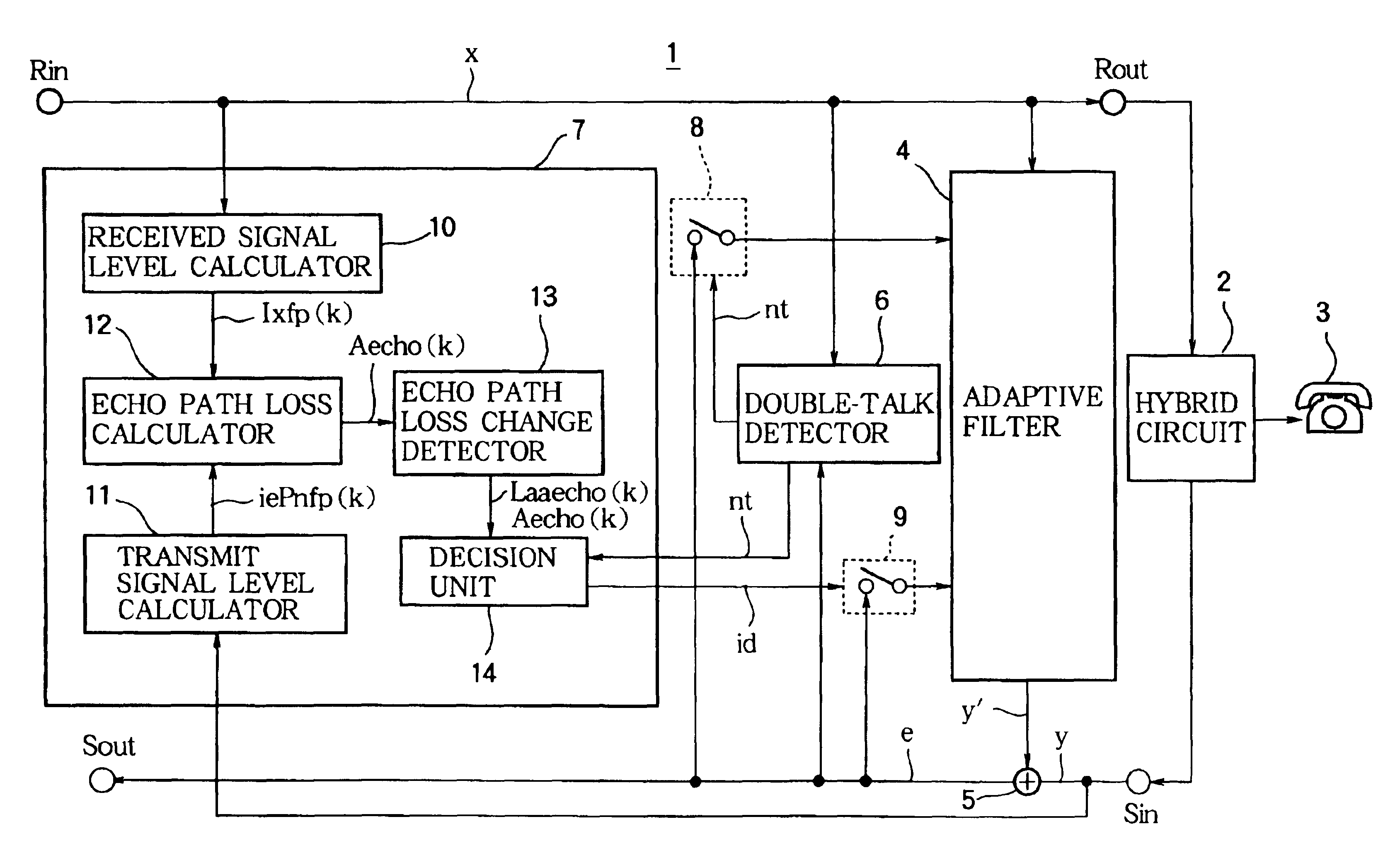
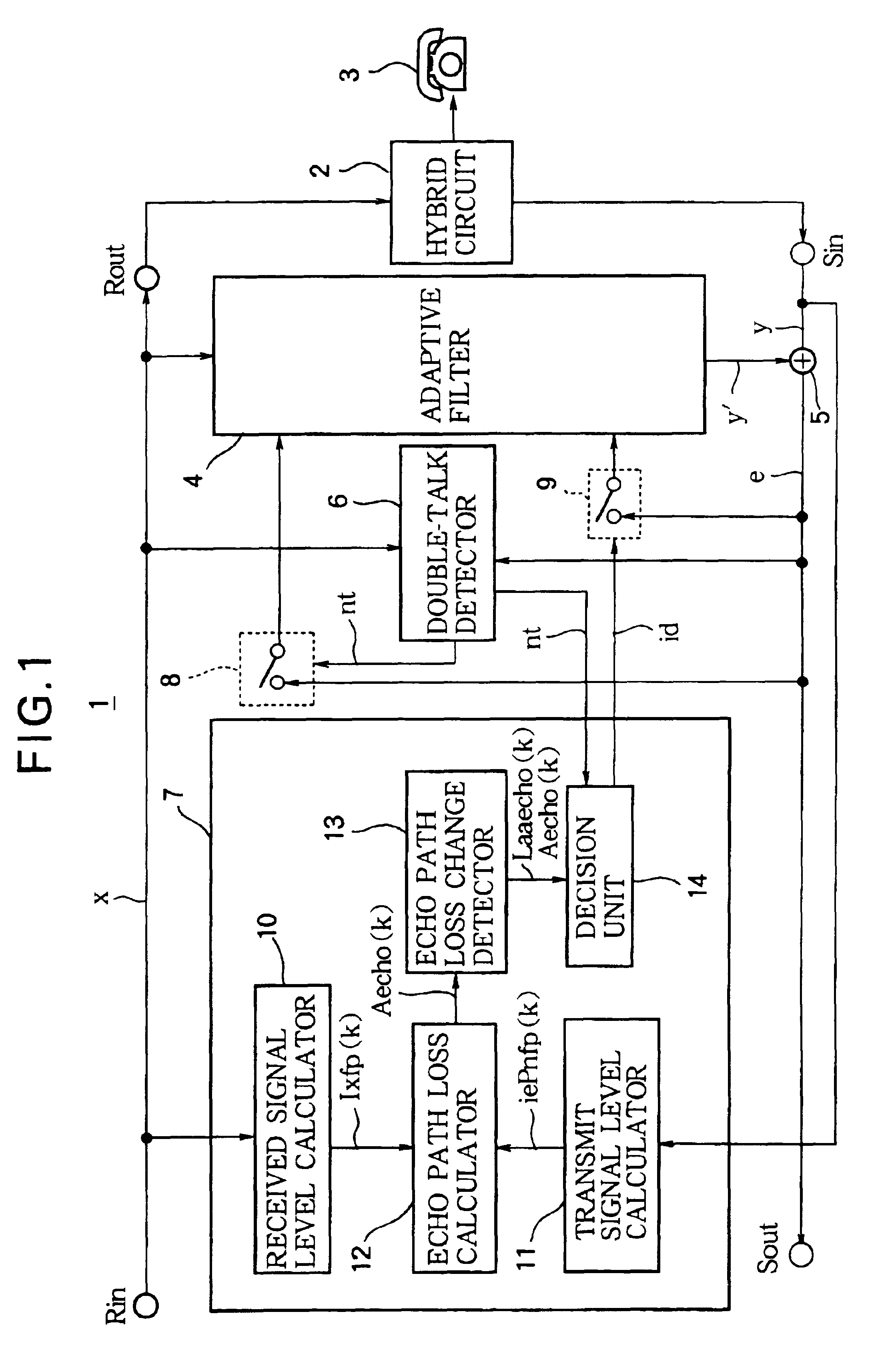
[0021]The first embodiment is illustrated in FIG. 1. A far-end signal (x) from a distant party is received at a receiving input terminal (Rin) of the echo canceler 1, passes unchanged through the echo canceler 1 in digital form, is output from a receiving output terminal (Rout) and through a hybrid circuit 2 to a telephone set 3, and is reproduced by a receiver or loudspeaker (not shown) in a telephone set 3. A microphone (not shown) in the telephone set 3 also obtains a near-end signal, which is routed through the hybrid circuit 2 to a sending input terminal (Sin) of the echo canceler 1 and is transmitted from a sending output terminal (Sout) of the echo canceler 1 back to the far end.
[0022]Although the purpose of the hybrid circuit 2 is to connect the transmitting and receiving paths separately to the telephone set 3, part of the received far-end signal (x) leaks through the hybrid circuit 2 onto the transmitting path, giving rise to an echo referred to as a line echo. In addition...
second embodiment
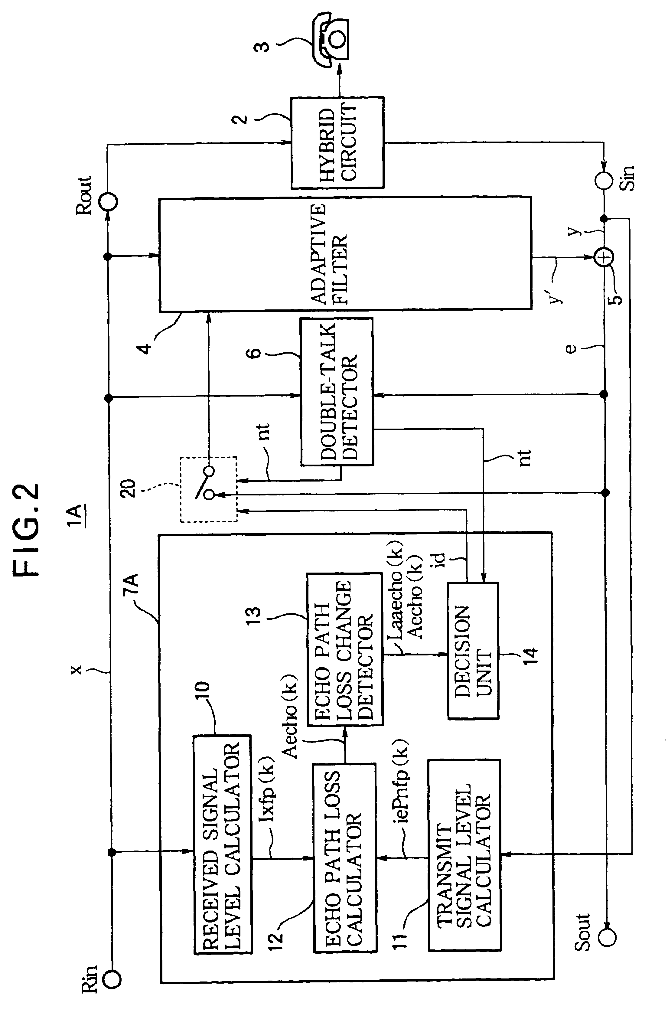
[0060]The second embodiment is illustrated in FIG. 2. The echo canceler 1A differs from the echo canceler 1 in the first embodiment by replacing the pair of switches8 and 9 with a single switch 20 that combines the functions of switches 8 and 9.
[0061]Switch 20 receives the adaptation-halting signal (nt) from a double-talk detector 6 and the echo path change detection signal (id) from a decision unit 14 as control signals, and controls input of the transmit signal (e) from the adder 5 to the adaptive filter 4.
[0062]Normally, switch 20 opens when it receives the adaptation-halting signal (nt), and closes when it does not receive the adaptation-halting signal (nt). When switch 20 receives the echo path change detection signal (id), however, it remains closed even if it also receives the adaptation-halting signal (nt).
[0063]The echo canceler 1A in the second embodiment provides the same effects as in the first embodiment. Since the echo canceler 1A includes a single switch 20 for contro...
third embodiment
[0064]The third embodiment is illustrated in FIG. 3. The echo canceler 1B differs from the echo canceler 1A in the second embodiment by replacing the double-talk detector 6 and echo path change detector 7 and with a different double-talk detector 6B and echo path change detector 7B.
[0065]The echo path loss in a hybrid circuit 2 is generally 12 dB to 20 dB, or greater. In rare cases, however, the echo path loss in the hybrid circuit 2 may be as small as 6 dB to 12 dB, due to poor impedance matching between the hybrid circuit 2 and the telephone set 3. Typically, this results from manufacturing variations in the electrical characteristics of the hybrid circuit 2. In the third embodiment, such variations are taken into account so that changes in the echo path can be detected accurately even if the echo path loss is comparatively small.
[0066]When the echo path loss in the hybrid circuit 2 is small, the double-talk detection condition described in the first embodiment is frequently satis...
PUM
 Abstract
Description
Claims
Application Information
 - R&D
- Intellectual Property
- Life Sciences
- Materials
- Tech Scout
- Unparalleled Data Quality
- Higher Quality Content
- 60% Fewer Hallucinations
Browse by: Latest US Patents, China's latest patents, Technical Efficacy Thesaurus, Application Domain, Technology Topic, Popular Technical Reports.
© 2025 PatSnap. All rights reserved.Legal|Privacy policy|Modern Slavery Act Transparency Statement|Sitemap|About US| Contact US: help@patsnap.com


