Method and system for diagnosing machine malfunctions

a machine and malfunction technology, applied in the field of machine diagnostics, can solve the problem of almost impossible pre-definition and achieve the effect of avoiding the formation of the structure of the cas

Inactive Publication Date: 2005-09-20
WESTINGHOUSE AIR BRAKE TECH CORP
View PDF69 Cites 203 Cited by
  • Summary
  • Abstract
  • Description
  • Claims
  • Application Information

AI Technical Summary

Problems solved by technology

Unfortunately, for a continuous fault code stream where any or all possible fault codes may occur from zero to any finite number of times and where the fault codes may occur in any order, predefining the structure of a case is nearly impossible.

Method used


Image

  • Method and system for diagnosing machine malfunctions
  • Method and system for diagnosing machine malfunctions
  • Method and system for diagnosing machine malfunctions

Examples


example 1

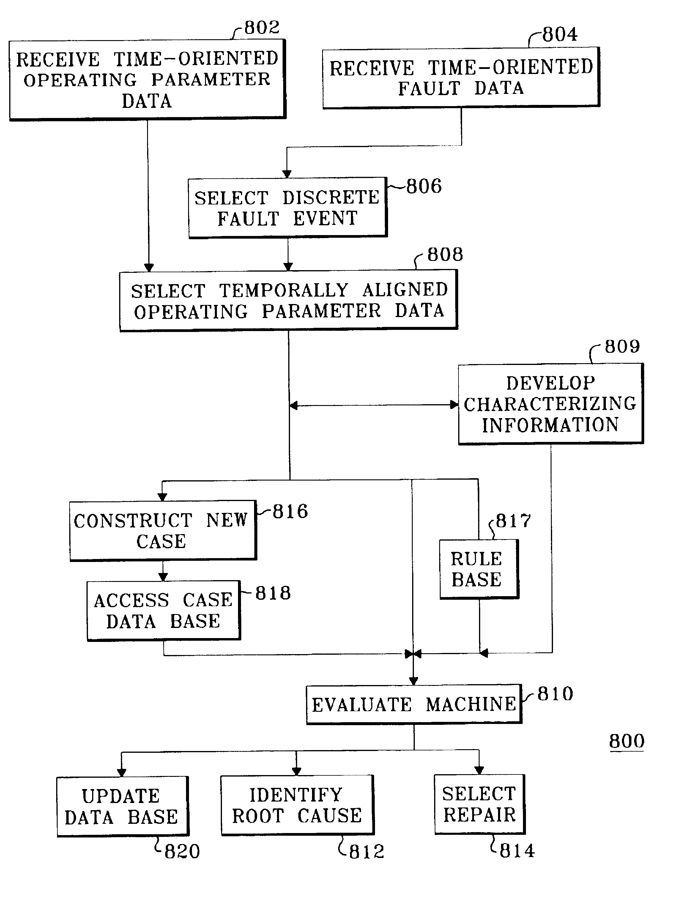
[0064]A fault indication of an excess current draw on a radiator fan motor is selected at step 806. Operational data is selected at step 808 to indicate the ground state of the auxiliary power supply that provides current to the fan motor at a time just prior to the time of the fault indication selected in step 806. Selectively focusing on the ground state just prior to the radiator fan motor current fault indication can provide information regarding the cause of the radiator fan motor problem; e.g. if the ground state is not normal, the excess current draw may be due to a grounding failure, but if the ground state is normal, the excess current draw may be due to a locked rotor or other such failure. The indication of the radiator fan motor excess current draw and the temporally aligned operating data regarding the ground state are then used together at step 810 to identify a likely cause of the radiator fan failure.

example 2

[0065]A fault indication of a diesel engine failure is selected at step 806. Sequential operating parameter data indicating the engine coolant temperature over a time interval shortly after the time of the logging of the fault is selected at step 808. This selectively focused subset of the temperature data gives an indication of whether the failure has progressed or whether it was caused by a transient condition. The indication of the diesel engine failure and the coolant temperature sequence after the failure indication are then used at step 810 to identify a likely cause of the failure.

example 3

[0066]A fault indication of an engine high temperature alarm is selected at step 806. At step 808 we selectively focus on operational data indicating the change in engine temperature over a one-minute interval just prior to the fault alarm. The sequential operational data from this selectively focused time interval provides an indication of a rate of change in temperature, i.e. a slope or first derivative of the operating parameter. Knowing such first derivative information can provide an indication of whether the fault was due to a catastrophic failure of the cooling system. The indication of high temperature and the first derivative of the temperature data are used at step 810 to identify a likely cause of the fault with a higher probability of successfully identifying the actual failure than would otherwise be possible by using just the fault indication data.

[0067]The analyses of fault log data in method 800 of FIG. 11 may further include an automated case analysis process as des...


PUM


Abstract

A system (830) and method (800) for diagnosing a malfunctioning machine. A fault event is selected (806) together with sequential operating parameter data (808) from a selectively focused time interval about the fault event for evaluation of a machine (810). The selectively focused time interval may include data occurring just before, just after, or spanning the fault event. Characterizing information such as slope, rate of change, and absolute sign of the data may be derived (809) from the operating parameter data over the selectively focused time interval and used in the diagnosis. The fault event and operating parameter data may be compared to existing cases in a case database (834). A set of rules (817) or candidate anomalies (841) may be executed over the operating parameter data to further improve the accuracy of the diagnosis.

Description

[0001]This application is continuation-in-part of U.S. patent application Ser. No. 09 / 688,105, filed Oct. 13, 2000, now U.S. Pat. No. 6,636,771 dated Oct. 21, 2003, which, in turn, claims benefit of United States provisional patent application number 60 / 162,045 filed Oct. 28, 1999, and further is a continuation-in-part of U.S. patent application Ser. No. 09 / 285,611, filed Apr. 2, 1999, now U.S. Pat. No. 6,343,236 dated Jan. 29, 2002.FIELD OF THE INVENTION[0002]This invention relates generally to machine diagnostics, and more specifically to a system and method for processing fault log data and operating parameter data for analyzing a malfunctioning machine and for making repair recommendations for the machine.BACKGROUND OF THE INVENTION[0003]A machine such as locomotive includes elaborate controls and sensors that generate faults when anomalous operating conditions of the locomotive are encountered. Typically, a field engineer will look at a fault log and determine whether a repair ...

Claims


Application Information

Patent Timeline
Patent Type & Authority Patents(United States)
IPC IPC(8): B61C17/12B61C17/00B61C17/04G05B23/02G06F11/25G06F11/22
CPCB61C17/04B61C17/12G06F11/2257G06F11/2268G05B23/0278G05B23/0281Y02T30/10Y10S707/99945Y10S706/911Y10S706/912Y10S707/99948Y10S706/915Y10S706/914Y10S706/916Y10S706/917Y10S706/913Y10S706/918Y02T30/00
Inventor DEAN, JASON ARTHURRODDY, NICHOLAS EDWARD
Owner WESTINGHOUSE AIR BRAKE TECH CORP
Why Eureka
Try Eureka