Vacuum cleaner with noise suppression features

a vacuum cleaner and noise suppression technology, applied in the field of vacuum cleaners, can solve the problems of increasing the level of noise generated by the vacuum cleaner, and achieve the effect of facilitating the separation of contaminants

Inactive Publication Date: 2005-09-27
ROYAL APPLIANCE MFG
View PDF29 Cites 24 Cited by
  • Summary
  • Abstract
  • Description
  • Claims
  • Application Information

AI Technical Summary

Benefits of technology

[0009]More particularly in accordance with this aspect of the invention, the vacuum cleaner includes a cyclonic airflow chamber that facilitates the separation of contaminants from a suction airstream, the airflow chamber including a chamber inlet and a chamber outlet, the chamber inlet being fluidically connected with at least one of a suction nozzle and an above-the-floor cleaning tool; an exhaust filter housing including a suction duct and an exhaust plenum, the suction duct communicating with the chamber outlet; a suction source housing including an open end communicating with the exhaust plenum and a closed end; and a suction source positioned within the suction source housing to define an annular exhaust flow passageway surrounding the suction source from the housing closed end to the housing open end, the suction source including a suction inlet communicating with the suction duct and an exhaust outlet communicating with the housing closed end.

Problems solved by technology

However, increasing the suction power of a vacuum cleaner generally results in increasing the level of noise that is generated by the vacuum cleaner during cleaning operations.

Method used


Image

  • Vacuum cleaner with noise suppression features
  • Vacuum cleaner with noise suppression features
  • Vacuum cleaner with noise suppression features

Examples


Embodiment Construction

[0019]Referring now to the drawings, wherein the showings are for purposes of illustrating a preferred embodiment of the invention only and not for purposes of limiting same, there is shown a particular type of upright vacuum cleaner in which the subject noise suppression features are embodied. While the noise suppression features can be employed in this type of vacuum cleaner, it should be appreciated that it can be used in other types of vacuum cleaners as well.

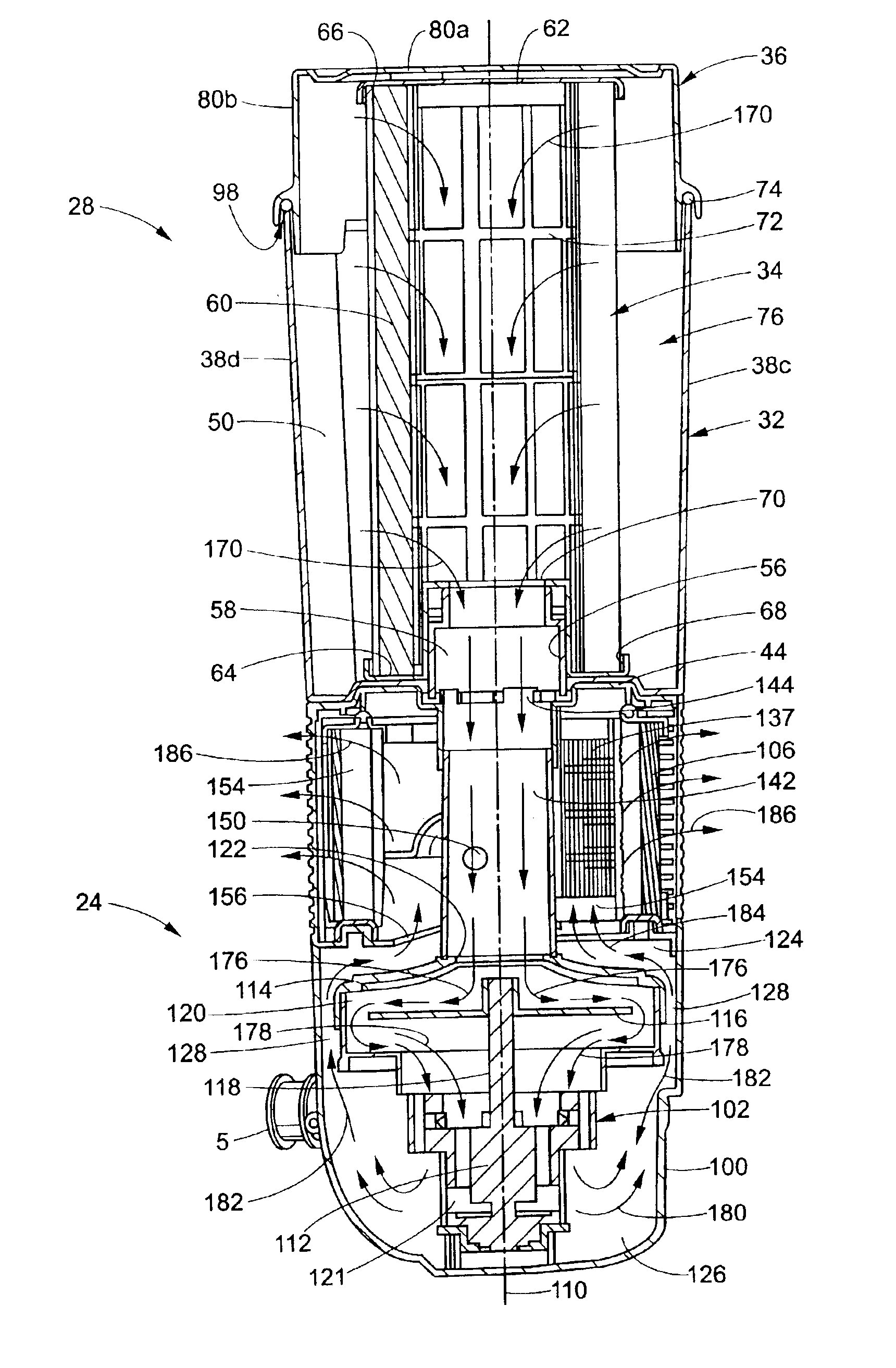
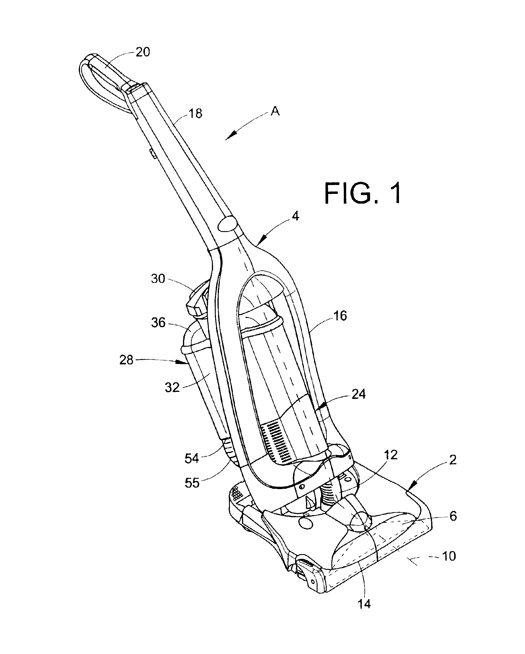
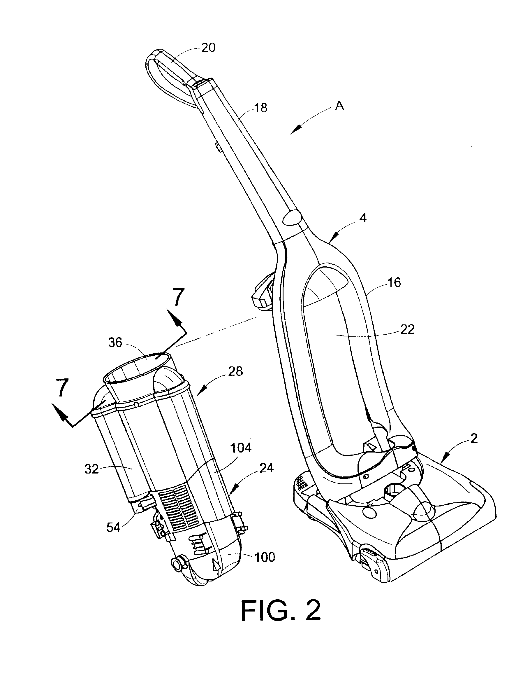
[0020]More particularly, FIG. 1 illustrates a vacuum cleaner A including a wheeled floor nozzle or nozzle base 2 and an upper assembly 4. The nozzle base 2 and the upper assembly are preferably formed from conventional materials such as molded plastics and the like. As best shown in FIG. 5, the upper assembly 4 is pivotally secured to the nozzle base 2 via trunnions 5 associated with a filter housing 100. Referring again to FIG. 1, the nozzle base 2 includes a downwardly opening brushroll chamber or cavity 6 (shown in phant...


PUM


Abstract

A vacuum cleaner includes a cyclonic airflow chamber that facilitates the separation of contaminants from a suction airstream. The airflow chamber includes a chamber inlet and a chamber outlet, with the chamber inlet being fluidically connected with at least one of a suction nozzle and an above-the-floor cleaning tool. An exhaust filter housing includes a suction duct and an exhaust plenum, with the suction duct communicating with the chamber outlet. A suction source housing includes an open end communicating with the exhaust plenum and a closed end. A suction source is positioned within the suction source housing to define an annular exhaust flow passageway surrounding the suction source from the housing closed end to the housing open end. The suction source includes a suction inlet communicating with the suction duct and an exhaust outlet communicating with the housing closed end.

Description

[0001]This application is a continuation of prior application U.S. Ser. No. 09 / 759,437, filed on Jan. 12, 2001, and issued as U.S. Pat. No. 6,532,621 on Mar. 18, 2003.BACKGROUND OF THE INVENTION[0002]This invention relates to vacuum cleaners. More particularly, it relates to a vacuum cleaner that provides increased suction power while reducing undesirable noise that is generated during operation of the vacuum cleaner.[0003]It is considered desirable to provide vacuum cleaners with strong suction power. However, increasing the suction power of a vacuum cleaner generally results in increasing the level of noise that is generated by the vacuum cleaner during cleaning operations.[0004]Accordingly, it is considered desirable to develop a new and improved vacuum cleaner with strong suction power and noise suppression features that meets the above-stated needs and overcomes the foregoing difficulties and others while providing better and more advantageous results.BRIEF SUMMARY OF THE INVEN...

Claims


Application Information

Patent Timeline
Patent Type & Authority Patents(United States)
IPC IPC(8): A47L9/16A47L9/22A47L9/10A47L9/12A47L9/00
CPCA47L5/28A47L9/0081A47L9/127A47L9/1409A47L9/165A47L9/1666A47L9/22Y10S55/03
Inventor STEPHENS, PAUL D.KALMAN, JEFFREY M.PALIOBEIS, STEVEN J.THUR, CHARLES J.
Owner ROYAL APPLIANCE MFG
Why Eureka
Try Eureka