Eureka AIR delivers breakthrough ideas for toughest innovation challenges, trusted by R&D personnel around the world.

Cutting subassembly

a sub-assembly and cutting technology, applied in the direction of other plywood/veneer working apparatus, manufacturing tools, metal sawing devices, etc., can solve the problems of high labor intensity, high cost, and difficulty in carrying out the work of skilled personnel

Inactive Publication Date: 2005-09-27
REICH SPEZIALMASCH
View PDF13 Cites 4 Cited by
  • Summary
  • Abstract
  • Description
  • Claims
  • Application Information

AI Technical Summary

Benefits of technology

[0010]It is advantageous if the saw blade, in the second operating position, can be positioned at an angle of up to approximately 15° in relation to the contact surface.
[0022]The spring element may be configured, for example, as a spring bolt which can be engaged against the horizontal carriage. It has proven particularly advantageous if in each case two stops are associated with a common spring bolt which, as the saw unit approaches the two stops, subjects the saw unit to a spring force.

Problems solved by technology

Orienting the saw blade obliquely in relation to the contact surface, in the case of known cutting subassemblies, necessitates high-outlay conversion, which can only be carried out by skilled personnel.
This conversion is associated with a considerable outlay in terms of time and costs.

Method used


Image

  • Cutting subassembly
  • Cutting subassembly
  • Cutting subassembly

Examples


Embodiment Construction

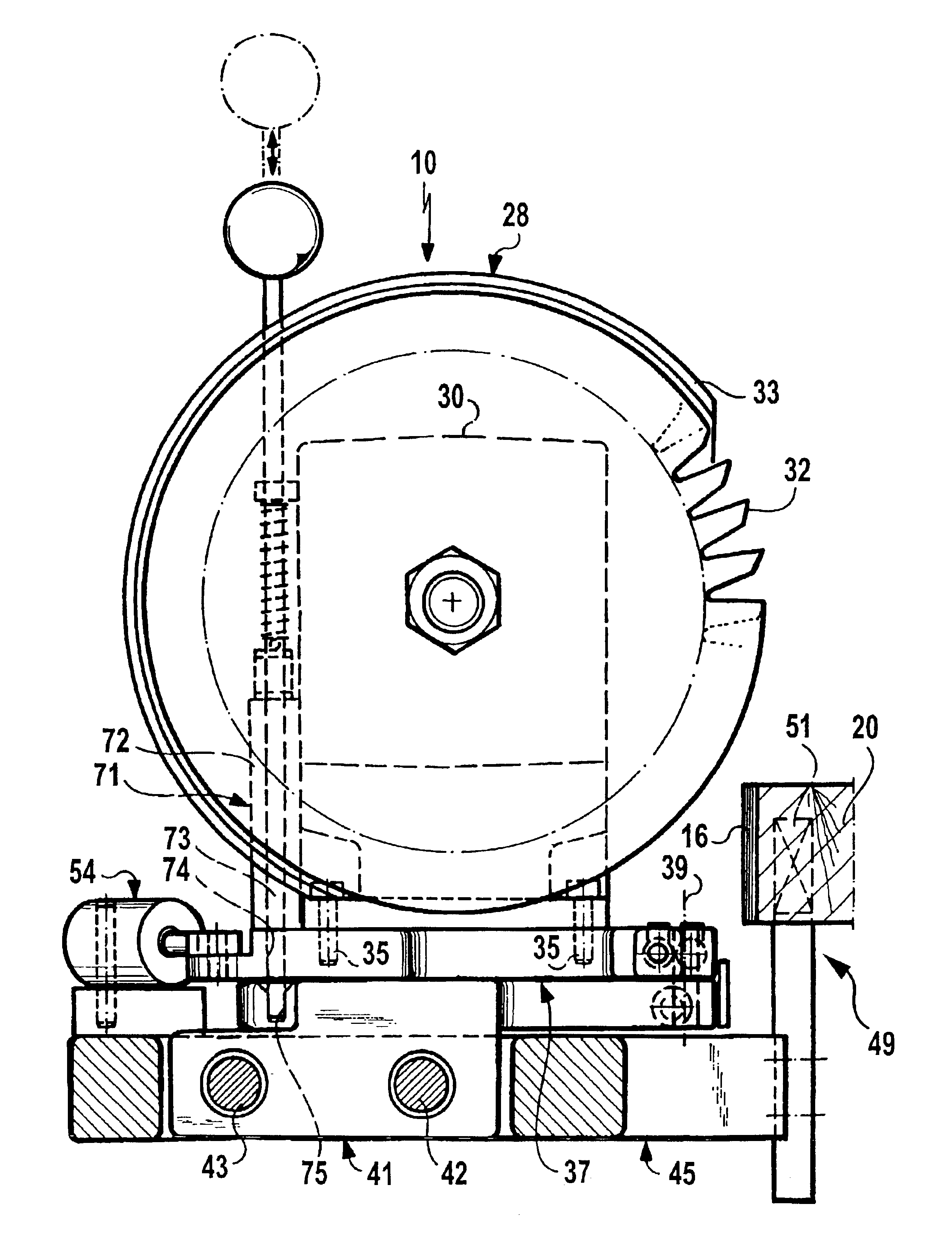
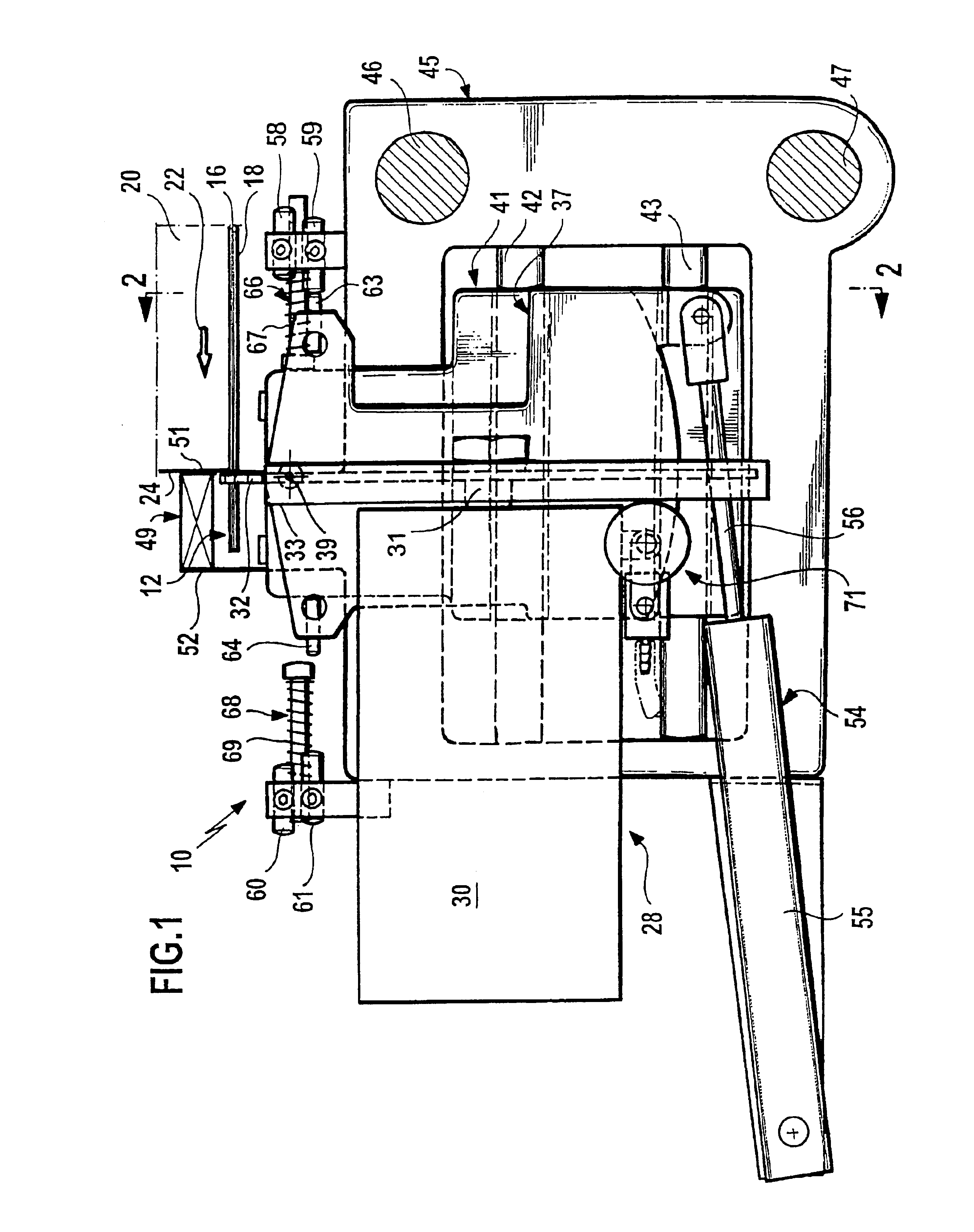
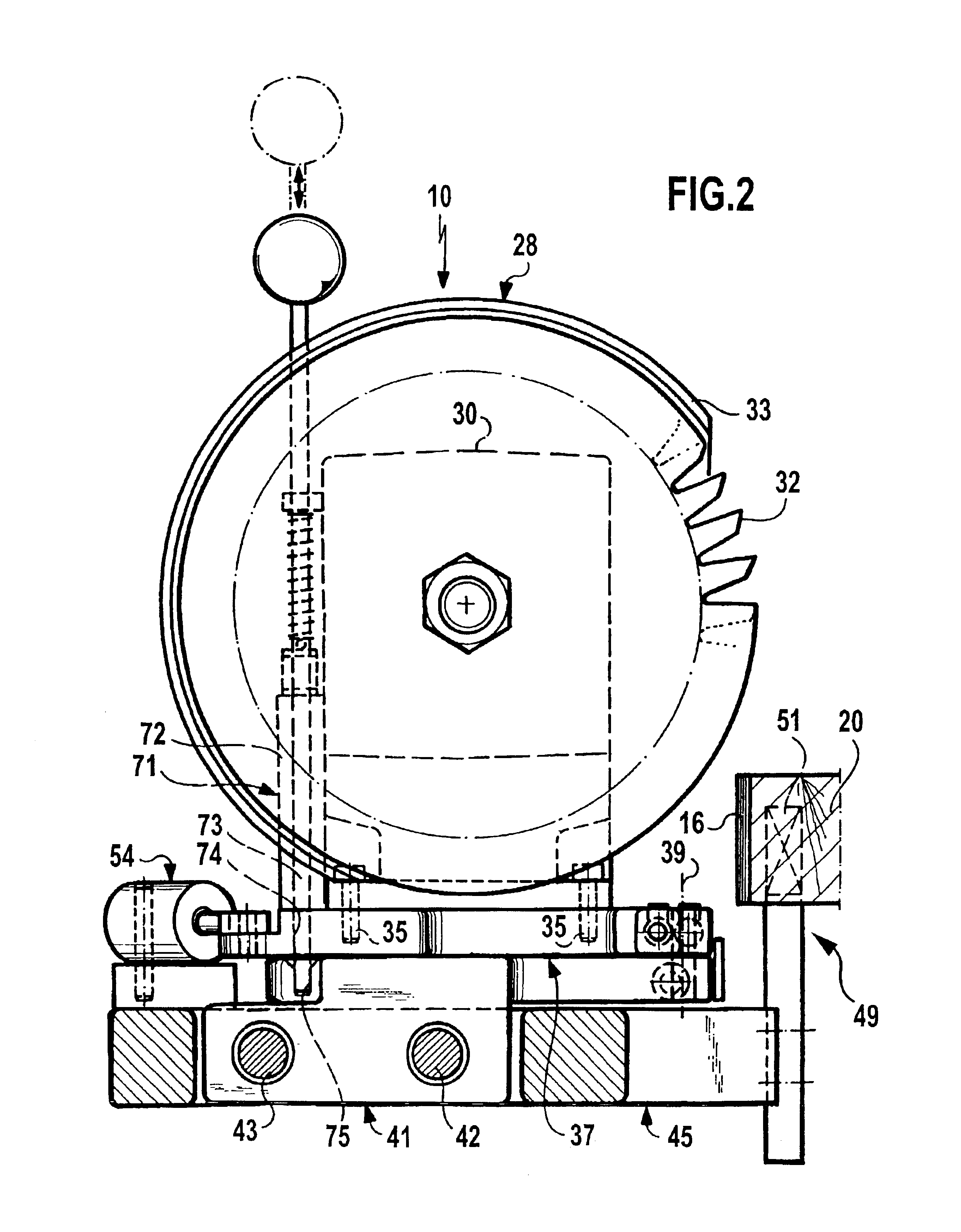
[0028]The drawings illustrate, schematically, a cutting subassembly which is designated overall by the reference sign 10 and is intended for cutting off a front edge overhang 12 and a rear edge overhang 14 of a glue-on edge 16 which has been glued onto a longitudinal side 18 of a workpiece 20. The cutting subassembly 10 forms one of a number of stations of a machine for machining panel-like workpieces which are moved continuously in a rectilinear manner along a workpiece-passage plane. In this case, in a glue-on station disposed upstream of the cutting subassembly 10, the glue-on edge 16 is glued onto the longitudinal side 18 of the workpiece 20. The glued-on edge 16 projects forward beyond the front transverse side 24 and rearward beyond the rear transverse side 26 of the workpiece 20, as seen in the movement direction 22 of the workpiece 20, and forms the front and rear edge overhangs 12 and 14, respectively, in these regions.

[0029]In order to cut off the front and rear edge overh...


PUM

PropertyMeasurementUnit
angleaaaaaaaaaa
angleaaaaaaaaaa
angleaaaaaaaaaa

Abstract

The invention relates to a cutting subassembly for cutting off front and / or rear edge overhangs of panel-like workpieces. The cutting subassembly includes a saw unit which comprises a motor-driven saw blade which is mounted for displacement between a position above, and a position beneath, the workpiece. A contact element is associated with the saw blade and has at least one contact surface which may be engaged against the front or rear transverse side of the workpiece. The cutting plane of the saw blade may be oriented in alignment with the contact surface. The saw blade may be mounted such that it can be pivoted between a first operating position, in which it is oriented in alignment with the contact surface, and a second operating position, in which it is oriented obliquely in relation to the contact surface.

Description

[0001]The present disclosure relates to the subject matter disclosed in International patent application No. PCT / EP02 / 01607 of Feb. 15, 2002, which is incorporated herein by reference in its entirety and for all purposes.BACKGROUND OF THE INVENTION[0002]The invention relates to a cutting subassembly for machines. A panel-like workpiece is moved continuously in a rectilinear manner in order for edge-material overhangs projecting beyond the front and / or rear transverse sides of the workpiece, which are oriented substantially transversely to the movement direction of the workpiece, to be cut off by a cutting subassembly. The cutting subassembly is provided on the longitudinal sides of the workpiece, the longitudinal sides running parallel to the movement direction. The cutting subassembly has a saw unit which comprises a motor-driven saw blade and which is mounted such that it can be displaced between a position above the workpiece and a position beneath the workpiece. The cutting suba...

Claims


Application Information

Patent Timeline
Patent Type & Authority Patents(United States)
IPC IPC(8): B23D45/02B23D45/20B27D5/00
CPCB23D45/024B23D45/20B27D5/006Y10T83/8773Y10T83/6667Y10T83/7772Y10T83/7705Y10T83/778Y10T83/7768Y10T83/7776Y10T83/7763Y10T83/7726
Inventor HENZLER, ROLANDBINDER, WERNER
Owner REICH SPEZIALMASCH
Why Eureka
Eureka Blog
Learn More