Collapsible stand for parking bicycles or the like

a technology for bicycles and racks, applied in the field of stand or racks, can solve the problems of affecting the operation, the angular relationship of the modules may be subject to change, and the disadvantages of construction and/or operation, and achieve the effect of reducing the space occupied by the stand or rack

Inactive Publication Date: 2005-09-27
SARIS CYCLING GROUP
View PDF28 Cites 12 Cited by
  • Summary
  • Abstract
  • Description
  • Claims
  • Application Information

AI Technical Summary

Benefits of technology

[0004]It is an object of the present invention to provide a portable, collapsible rack or stand for supporting bicycles or the like in an upright position, in which the components of the rack or stand are assembled together and cannot be removed, to ensure that the components cannot be lost or misplaced. It is a further object of the invention to provide such a rack or stand which provides a consistent position when the rack or stand is in the unfolded position for use. Another object of the invention is to provide such a rack or stand having a hinge arrangement for providing movement of the rack or stand between a folded condition and an unfolded condition, and including a stop arrangement that is independent of the hinge arrangement for providing consistent conditioning of the components of the rack or stand in the unfolded use position. Yet another object of the invention is to provide such a rack or stand that is relatively simple in its components, construction and operation, yet which provides consistent, reliable operation and is easy to fold for storage or transport.
[0007]The hinge barrels are positioned relative to the upper members such that the pivot axis defined by the hinge pin is located below a center defined by each of the upper members. With this arrangement, pivoting movement of the supports from the closed, collapsed position toward the open, operative position results in engagement of facing areas of the upper members with each other at a location above the pivot axis. Such engagement of the upper members functions as a stop so as to place the supports in a predetermined angular orientation when the supports are moved apart. To collapse the rack or stand for transport or storage, the supports are pivoted toward each other about the pivot axis defined by the hinge pin. The supports are configured so as to assume a generally parallel orientation when in the closed, collapsed position, to minimize the space occupied by the stand or rack.

Problems solved by technology

While a rack as disclosed in the '461 patent is portable and collapsible so as to be capable of use in the noted applications, there are certain features of this type of rack that present disadvantages in construction and / or operation.
In the event the nuts are not sufficiently tightened against the top tube ends, the angular relationship of the modules may be subject to change if the rack is bumped or struck after the position of the modules has initially been set.

Method used


Image

  • Collapsible stand for parking bicycles or the like
  • Collapsible stand for parking bicycles or the like
  • Collapsible stand for parking bicycles or the like

Examples


Embodiment Construction

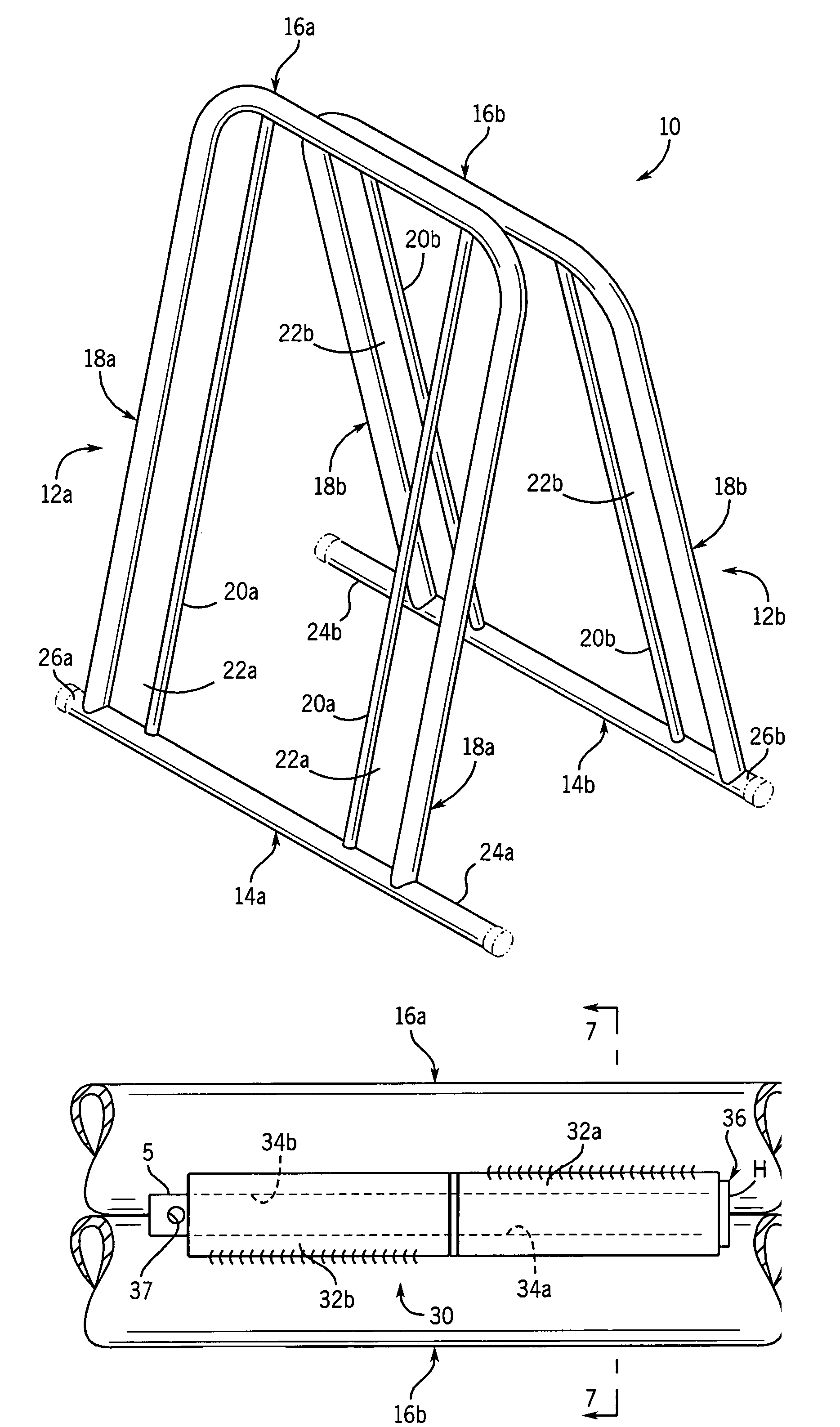
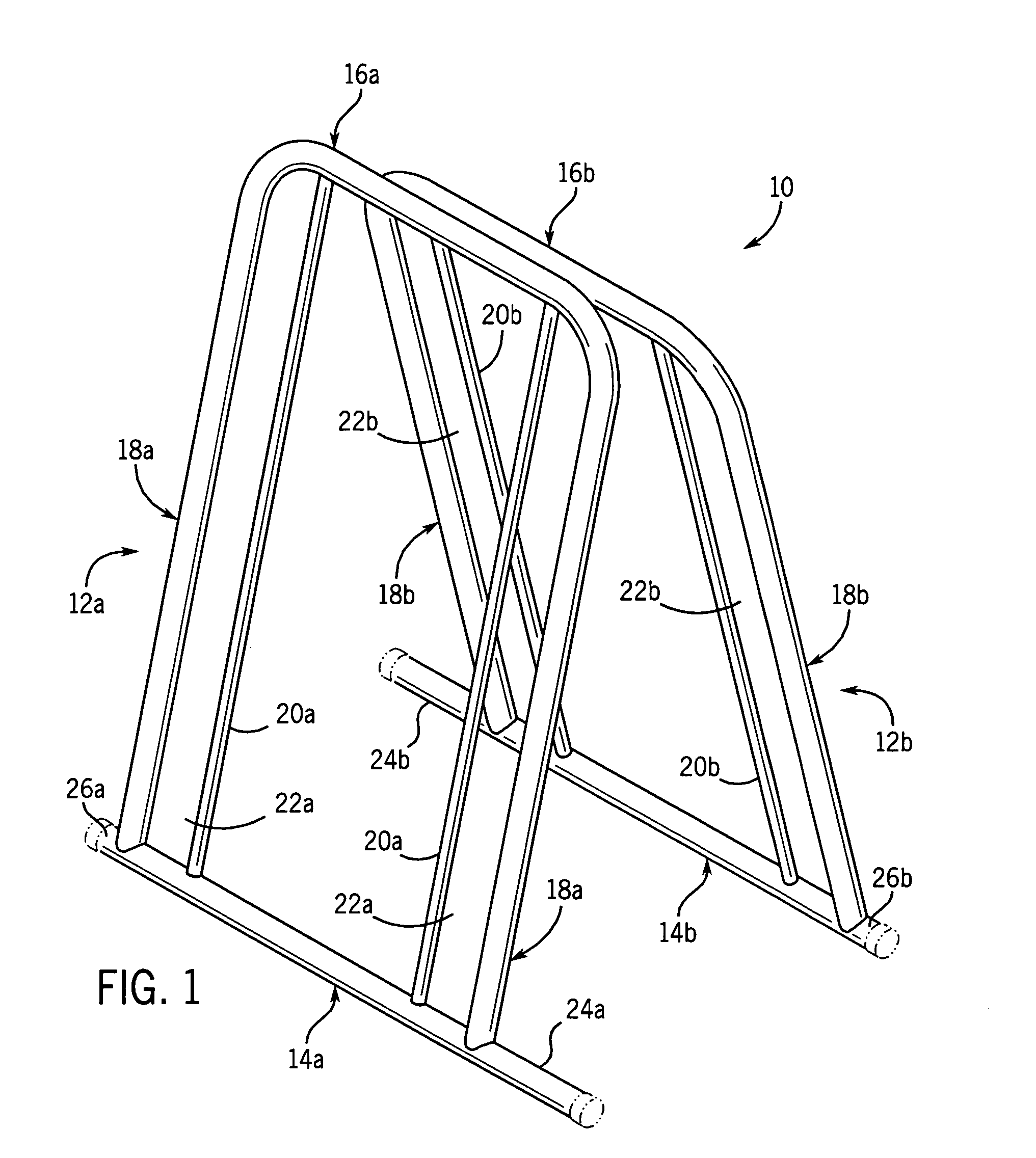
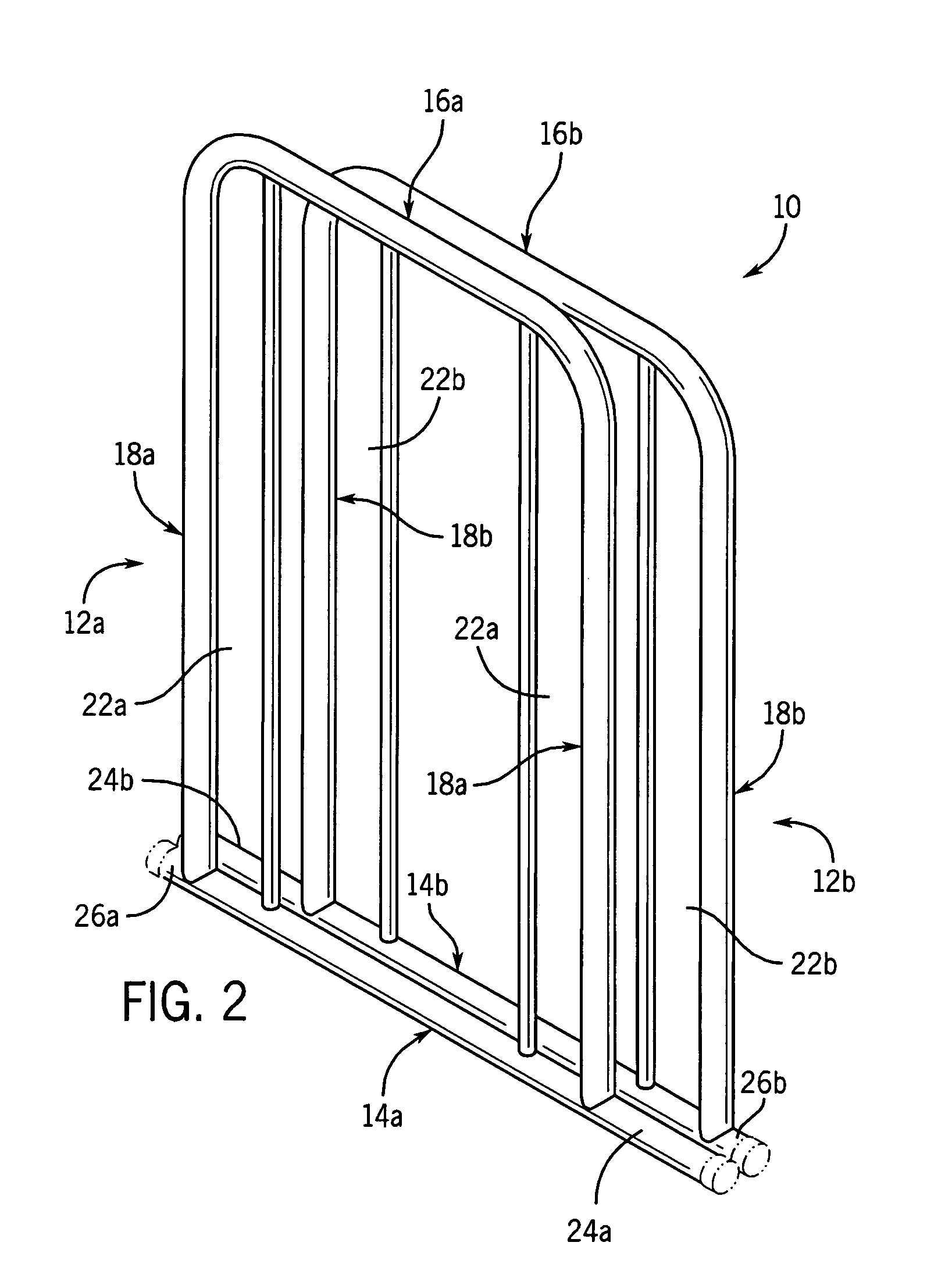
[0019]A parking rack or stand 10, for use in parking a bicycle or the like, includes a pair of supports 12a, 12b that are pivotably interconnected, in a manner to be explained, for movement between an open or unfolded, operative use position as shown in FIG. 1 and a closed or folded, inoperative position as shown in FIG. 2 for transport or storage. In the illustrated embodiment, supports 12a and 12b are identical in construction, and are arranged in a laterally offset manner facing each other.

[0020]Supports 12a, 12b include respective lower members 14a, 14b and respective upper members 16a, 16b. A pair of side members 18a extend between and interconnect lower member 14a and upper member 16a, and a pair of side members 18b extend between and interconnect lower member 14b and upper member 16b. In the illustrated embodiment, upper members 16a, 16b and respective side members 18a, 18b are formed of a single length of bent tubular material, the ends of which are secured to respective low...


PUM


Abstract

A collapsible rack or stand for supporting a bicycle or the like in an upright position includes a pair of supports that are pivotably interconnected together for movement between an open, operative position and a closed, inoperative position. Each support defines one or more vertically extending spaces, each of which is configured to receive one of the bicycle wheels for supporting the bicycle in an upright position when the supports are in the open, operative position. Each support includes a lower member and an upper member, between which the wheel-receiving spaces are located, and the upper members of the supports are pivotably interconnected via a hinge arrangement for enabling movement of the supports between the open, operative position and the closed, inoperative position. The hinge arrangement is in the form of a hinge barrel secured to the upper member of each support, and the hinge barrels define aligned passages through which a hinge pin extends. The hinge barrels are configured and arranged such that the upper members of the supports are moved into engagement with each other when the supports are moved away from the closed, inoperative position so as to place the supports in the open, operative position, thus providing a stop for consistently positioning the supports in a predetermined angular relationship when the supports are moved to the open, operative position. The supports may be identically constructed, and are preferably connected together so that the spaces of the supports are offset from each other to enable bicycle wheels to be engaged with the supports in a staggered manner from opposite sides of the stand.

Description

BACKGROUND AND SUMMARY OF THE INVENTION[0001]This invention relates to a stand or rack for use in maintaining a bicycle or the like in an upright position, and more particularly to a parking stand or rack that is collapsible when not in use.[0002]There are many known types of parking stands or racks that are designed to maintain a bicycle or the like in an upright position. Typically, a parking stand or rack includes a lower support area which engages a lower area of one of the bicycle wheels, and an upwardly extending section, which may be in the form of a pair of spaced apart bars that define a space configured to receive the bicycle wheel at a location above the lower support area. The bars engage the sides of the wheel, to maintain the bicycle in an upright position. This type of parking stand or rack is typically a self-supporting, stationary structure adapted to remain in a predetermined location, e.g. adjacent a building, park, train station, etc.[0003]Smaller, compact parkin...

Claims


Application Information

Patent Timeline
Patent Type & Authority Patents(United States)
IPC IPC(8): A47F7/00B62H3/06
CPCB62H3/06
Inventor LASSANSKE, TODD W.BUTTCHEN, BRIAN W.
Owner SARIS CYCLING GROUP
Why Eureka
Try Eureka