Apparatus for discharging pressurized liquids at elevated positions

a technology for pressurizing liquids and apparatuses, which is applied in the direction of liquid transferring devices, machine supports, other domestic objects, etc., can solve the problems of ineffective and inefficient methods, affecting the personal safety of users, and being able to spray only for a relatively short distance, so as to achieve simple and inexpensive design, construction and operation

Inactive Publication Date: 2005-09-27
JACOBS TODD
View PDF8 Cites 5 Cited by
  • Summary
  • Abstract
  • Description
  • Claims
  • Application Information

AI Technical Summary

Benefits of technology

[0006]Accordingly, it is a general object of the present invention to provide an improved apparatus for discharging pressurized liquids at elevated positions which is relatively simple and inexpensive in design, construction and operation.

Problems solved by technology

However, these prior art pressurized canisters used for killing wasps, bees, hornets and the like suffer from the disadvantage of being capable of applying a spray only for a relatively short distance, such as twenty feet or less.
These methods are ineffective and inefficient and many a times can jeopardize the personal safety of the user.
Furthermore, during certain weather conditions such as on a windy day, the spray from the pressurized canister for the relatively short distance will probably not even reach the nest and will thus be totally ineffective.
In addition, the spray being in the form of an insecticide may be toxic and harmful if it comes into contact with the user.

Method used


Image

  • Apparatus for discharging pressurized liquids at elevated positions
  • Apparatus for discharging pressurized liquids at elevated positions
  • Apparatus for discharging pressurized liquids at elevated positions

Examples


Embodiment Construction

[0020]It is to be distinctly understood at the outset that the present invention shown in the drawings and described in detail in conjunction with the preferred embodiments is not intended to serve as a limitation upon the scope or teachings thereof, but is to be considered merely as an exemplification of the principles of the present invention.

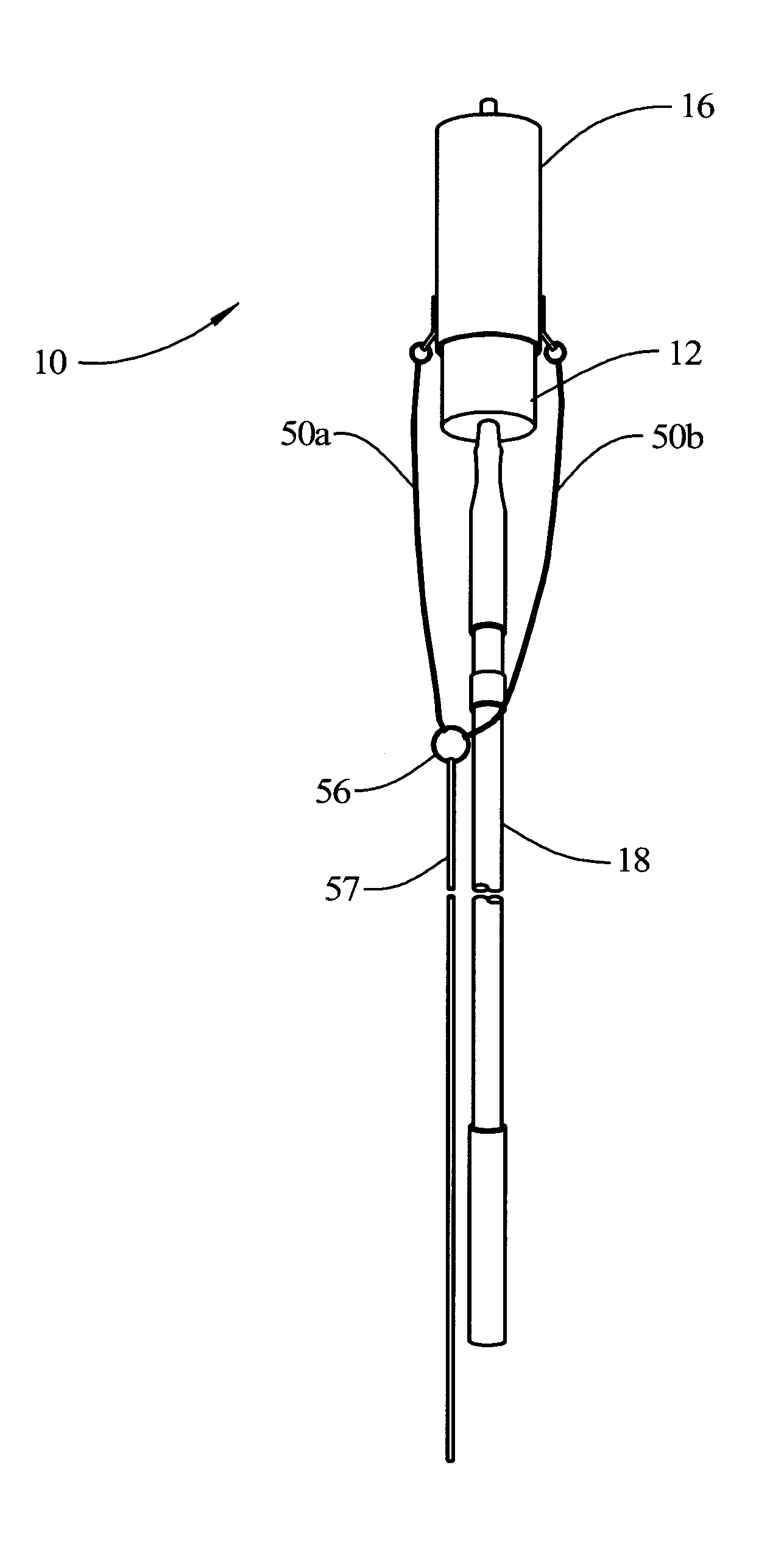
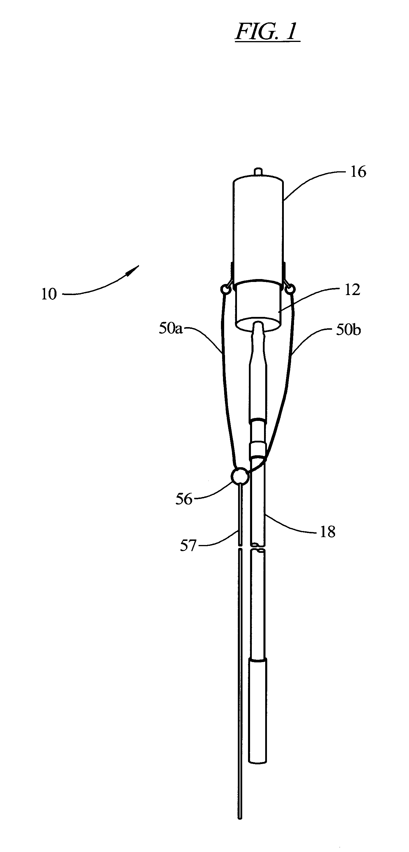
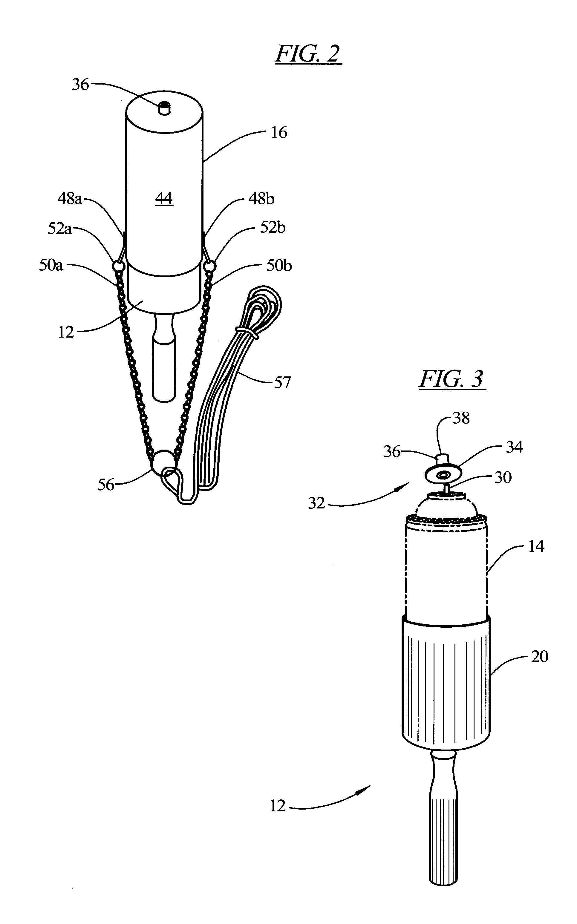
[0021]Referring now in detail to the drawings, there is illustrated in FIG. 1 an improved apparatus 10 for discharging pressurized liquids at elevated positions, constructed in accordance with the principles of the present invention and depicted in its fully assembled condition. FIG. 2 is a plan view of the apparatus 10, similar to that of FIG. 1, except that the adjustable extension pole 18 has been removed. FIG. 3 is a plan view of the holding adapter 12 of the present invention of FIG. 1. FIG. 4 is a perspective view of the holding adapter 12, similar to FIG. 3, but with the pressurized canister 14 being removed. FIG. 5 is a prospective vi...


PUM


Abstract

An apparatus for discharging pressurized liquids at elevated positions includes a holding adapter, an actuating assembly, and an extension pole. The holding adapter includes first body member for holding a canister of pressurized liquid. The canister has an actuating stem extending from its top end thereof. An actuator nozzle is formed of an annular flange and a cap-like head portion. The head portion is disposed over the actuating stem. A handle portion is formed integrally with the first body member and extending downwardly from the holding adapter. The actuating assembly is telescoped over the canister and the holding adapter and includes a second body member for applying a downward force on the annular flange of the actuating nozzle to activate the actuating for discharging the pressurized liquid therefrom. The extension pole is operatively connected to a distal end of the handle portion and is adjustable to desired elevated positions.

Description

BACKGROUND OF THE INVENTION[0001]This invention relates generally to apparatuses for discharging pressurized liquids and more particularly, the present invention relates to an improved apparatus for discharging pressurized liquids at elevated positions in an effective and efficient manner.[0002]As is generally well-known, pressurized containers or canisters housing various types of fluids, such as liquid insect sprays for killing wasps, bees, hornets and the like, are widely used in everyday life. Conventionally, these pressurized canisters include a cylindrically-shaped body of a predetermined length and an actuating stem disposed at a top end thereof. An actuating member or button is typically connected to the actuating stem which is manually operated by the index finger of a user or consumer. When the actuating member is depressed, the liquid contents of the pressurized canister is discharged or released therefrom in the form of a spray, i.e., liquid insect spray.[0003]However, t...

Claims


Application Information

Patent Timeline
Patent Type & Authority Patents(United States)
IPC IPC(8): B67D5/64B05B15/06B65D83/14B65D83/16B67D7/84
CPCB05B15/064B65D83/203B65D83/386B05B15/628
Inventor JACOBS, TODD
Owner JACOBS TODD
Why Eureka
Try Eureka