
Electronic operational control device for a piloting member with cross-monitoring, piloting device and aircraft

a piloting member and electronic technology, applied in the direction of actuating personally, process and machine control, instruments, etc., can solve the problems of low reliability, heavy implementation and operation costs, and devices that do not perform monitoring functions, etc., to improve reliability and operating safety, simple, light and compact

Active Publication Date: 2014-02-25
RATIER FIGEAC
View PDF17 Cites 3 Cited by
  • Summary
  • Abstract
  • Description
  • Claims
  • Application Information

AI Technical Summary

Benefits of technology

The invention is an electronic operational control device for aircraft that improves reliability and operating safety by monitoring the operation of the device using cross- redundant monitoring circuits. The device is simple, light, compact, inexpensive and compatible with industrial-scale manufacturing. It can detect any failure in the circuit used for monitoring, making it a reliable and safe solution for piloting the aircraft. The device is designed symmetrically, making it compatible with both pilot and copilot sticks without requiring modifications. This results in cost savings and easy manufacturing.

Problems solved by technology

This device does not perform a monitoring function.
In addition, such a device poses the problem of its reliability and of monitoring the occurrence of possible operating faults (failures) to ensure good operating safety.
EP 0 759 585 poses this problem and points out that such aeronautical systems must be fault tolerant and in particular integrate redundant devices.
Such a solution, which is traditional in its principle, is heavy, complex and costly in its implementation and its operation.
In addition, it remains imperfect insofar as certain failures which are liable to occur on such a monitoring computer will not necessarily be detected themselves.

Method used


Image

  • Electronic operational control device for a piloting member with cross-monitoring, piloting device and aircraft
  • Electronic operational control device for a piloting member with cross-monitoring, piloting device and aircraft
  • Electronic operational control device for a piloting member with cross-monitoring, piloting device and aircraft

Examples


Embodiment Construction

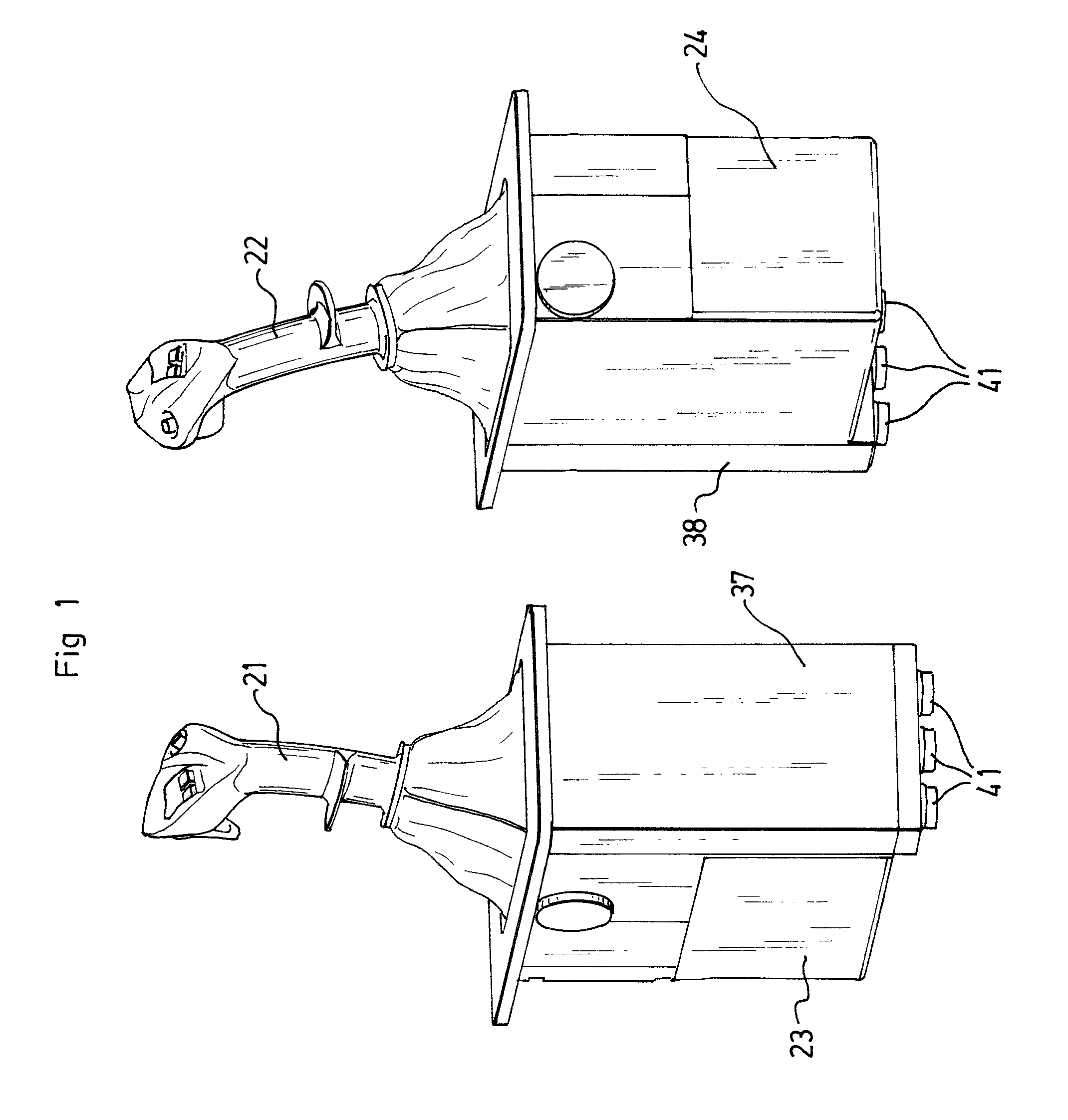
[0057]FIG. 1 shows a piloting device according to the invention which, in the example, comprises two pivoting mini-sticks 21, 22 for piloting an aircraft, one, 21, of which is intended to be used by the captain, and the other, 22, of which is intended to be used by the copilot.

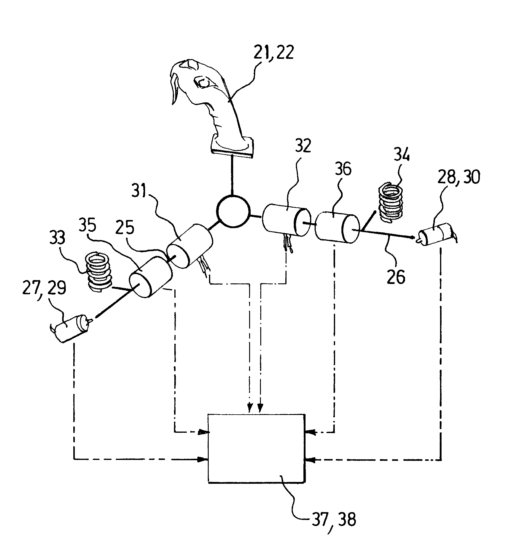
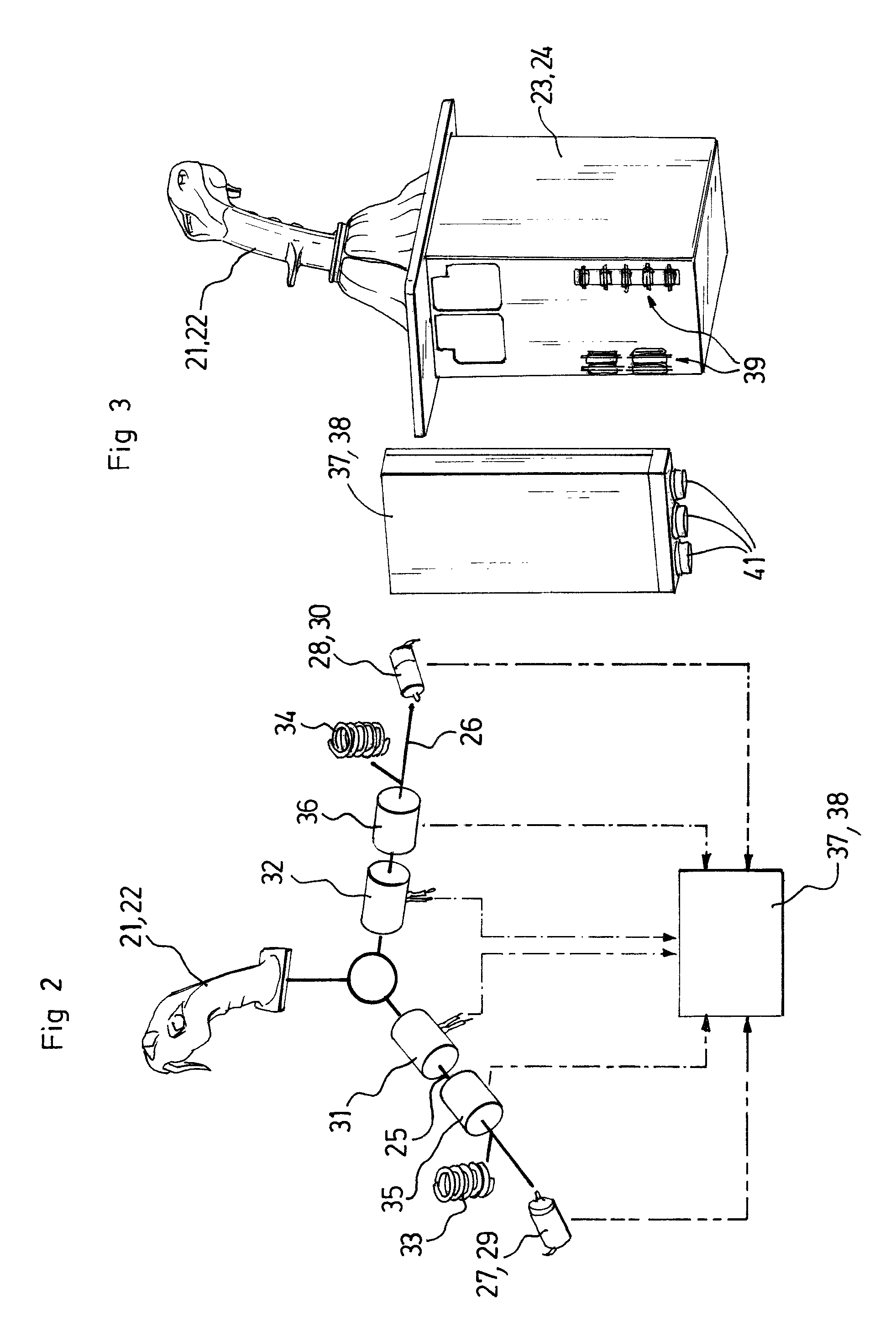
[0058]Each mini-stick 21, 22 is mounted on an electromechanical supporting box 23 and 24, respectively, which incorporates (FIG. 2) in particular the kinematics for guiding the mini-stick in rotation about the pitch axis 25 and the roll axis 26, and, for each of these axes, at least angular position sensors 27, 28, preferably also angular velocity sensors 29, 30 (in a variant not shown also angular acceleration sensors), and force sensors 31, 32, return springs 33, 34 associated with levers making it possible to return the mini-stick to the neutral position, and actuating motors (namely two motors 35a, 35b and 36a, 36b per axis, shown and designated collectively by the references 35, 36 in FIG. 2) making it po...


PUM


Abstract

An electronic operational control device for an aircraft piloting device with two connected piloting members, includes electronic circuits for main monitoring from signals delivered by sensors associated with one of the piloting members, and at least one electronic circuit (52 to 55) for cross-monitoring, for digital processing of signals delivered by sensors (83, 93) associated with the other piloting member, adapted to detect any deviation of these signals corresponding to a fault and to generate a signal representing such a fault. A piloting device and an aircraft including such an electronic operational control device with cross-monitoring are also disclosed.

Description

BACKGROUND OF THE INVENTION[0001]1. Field Of The Invention[0002]The invention relates to an electronic operational control device for a piloting member, called the controlled piloting member, of an aircraft comprising a piloting device equipped, for each flying member of the aircraft, with two such piloting members connected (by a completely mechanical kinematic chain or at least partly electrically) to this flying member, so that the aircraft can be piloted simultaneously by two people: a captain and a copilot. Throughout the text, the term “piloting” and its derivatives denote, unless otherwise stated, the flying of an aircraft by at least one human pilot operating at least one piloting member such as a stick, handle, rudder bar, pedal, etc., connected to at least one flying member such as a control surface or a throttle control of the aircraft, etc. The term “command” and its derivatives denote in the traditional manner in aeronautics the fact of supplying a device with signals w...

Claims


Application Information

Patent Timeline
IPC IPC(8): B25J19/02
CPCG05D1/0077B64C13/12
Inventor ANTRAYGUE, CEDRIC
Owner RATIER FIGEAC
Learn More