Aircraft one-piece fuel nonreturn device and method for manufacturing such a device

a one-piece, fuel-free technology, applied in the direction of valve details, valve housings, valve arrangements, etc., can solve the problems of non-return devices, manufacturing processes that are more complex, and components that make them up cannot allow electrical continuity between

Pending Publication Date: 2020-11-05
ZODIAC AEROTECHNICS
View PDF3 Cites 0 Cited by
  • Summary
  • Abstract
  • Description
  • Claims
  • Application Information

AI Technical Summary

Problems solved by technology

This type of nonreturn device generally has the disadvantage that the components that make it up do not allow electrical continuity between them.
To avoid the appearance of an electrostatic charge, which is an explosion hazard in the field of aeronautics, it is necessary to connect the components together, for example with conductive wires, or to implement additional surface treatments and protections, making the manufacturing process more complex and thus increasing its cost.
As a result, the design and manufacture of this type of nonreturn device is time-consuming, costly and tedious.
Furthermore, the available spring shapes are limited.
This gives the designer a limited choice of spring characteristics, such as e.g. the stiffness or progressiveness thereof.

Method used


Image

  • Aircraft one-piece fuel nonreturn device and method for manufacturing such a device

Examples


first embodiment

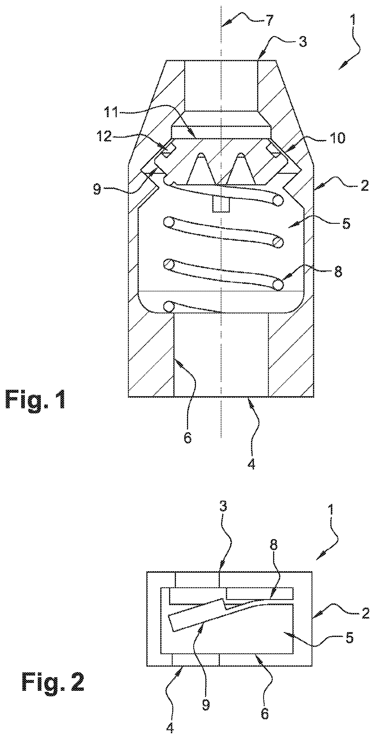
[0030]According to the invention, shown in FIG. 1, the device (1) comprises a body (2) that is substantially cylindrical, elongate and axially symmetrical. The body (2) has at its ends two openings, one upstream (3), the other downstream (4). The body (2) defines a chamber (5) intended for receiving the fluid that can flow from the upstream opening (3) towards the downstream opening (4), but which is prevented from returning towards the upstream opening (3), as will be explained in greater detail below. The terms “upstream” and “downstream” relate to the direction of flow of the fluid permitted by the nonreturn device (1).

[0031]The chamber (5) has an internal wall (6) with a tubular conformation along the central longitudinal axis (7), and has a variable diameter along the device (1).

[0032]The internal wall (6) is extended by an elastic return member (8) forming an integral part with said internal wall (6). According to this first embodiment, the elastic return member (8) is a helic...

second embodiment

[0040]In reference to FIG. 2, and the elastic return member is a leaf spring (8). The leaf spring (8) extends the internal wall (6) laterally, and is extended by the valve shutter (9), with the wall (6), the leaf spring (8) and the valve shutter (9) forming a one-piece assembly.

[0041]Of course, the leaf spring (8) can be manufactured in any appropriate manner, for example as a single leaf or as two leaves, one on either side of the valve shutter (9), etc. The leaf or leaves can have a variable section in order best to adapt the elastic behavior of the spring (8) to requirements.

[0042]Advantageously, the method for manufacturing the device (1) according to the invention consists of manufacturing, layer by layer and by additive manufacturing, the body (2), the elastic return member (8) and the valve shutter (9), so that the body (2), the elastic return member (8) and the valve shutter (9) together form a single one-piece part, the device (1) being manufactured so that:[0043]the body ...


PUM


Abstract

The invention relates to a fluid nonreturn device (1) comprising a body (2) defining a chamber (5) intended to receive a fluid and having at least one opening (3), the chamber (5) has an internal wall (6) extended by an elastic return member (8) which forms an integral part of said internal wall (6), said elastic return member (8) is extended by a valve shutter (9) forming an integral part of said elastic return member (8), the elastic return member (8) pushes the valve shutter (9) into a position in which it closes off the opening (3) so as to prevent the fluid in the chamber (5) from leaving via the opening (3).

Description

TECHNICAL FIELD[0001]The present invention relates to the technical field of fuel circulation in an aircraft, such as an airplane, a helicopter or other, and more particularly relates to a nonreturn device capable of being installed in the circuit, and a method for manufacturing said device.PRIOR ART[0002]Nonreturn devices such as ball valves, flap valves and the like are known from the prior art. Their operation consists of permitting a fluid, e.g. fuel, to flow in only one direction through a pipe. All these devices comprise several components. In particular, they comprise a spring-type elastic element which pushes a blocking element, such as a ball, a valve etc., into a closing position. Thus, the fluid, under a certain pressure, can flow against the blocking element by compressing the spring, but its return is blocked by said blocking element.[0003]This type of nonreturn device generally has the disadvantage that the components that make it up do not allow electrical continuity ...

Claims


Application Information

Patent Timeline
Patent Type & Authority Applications(United States)
IPC IPC(8): F16K27/02F16K15/02F16K15/14
CPCF16K15/14F16K15/026F16K27/0209
Inventor CORMAN, FRANÇOIS
Owner ZODIAC AEROTECHNICS
Why Eureka
Try Eureka