Horizontal wind generator

a generator and horizontal technology, applied in the direction of machines/engines, renewable energy generation, greenhouse gas reduction, etc., can solve the problem of increasing the speed of the windmill blade, and achieve the effect of cost-effectiveness

Inactive Publication Date: 2005-09-27
HORJUS THOMAS W
View PDF18 Cites 29 Cited by
  • Summary
  • Abstract
  • Description
  • Claims
  • Application Information

AI Technical Summary

Benefits of technology

[0005]In accordance with the present invention, a horizontal windmill and electrical generator assembly comprises a vertical drive shaft mounted for rotation in a base, with the drive shaft extending upwardly into a wind catching position and with a plurality of drive units being mounted at spaced axial locations along the drive shaft. The drive units comprise oppositely facing wind catching elements or wind catchers mounted on the ends or at spaced locations along crossbars non-rotatably attached to the pole. Multiple drive units are used, with each drive unit being spaced axially from the other drive units and angularly disposed from adjacent units at regular intervals around the pole. Two or four spaced drive units are particularly desirable. Wind catchers formed of cup shaped bowls or split barrels are particularly effective and are cost effective.

Problems solved by technology

A problem with this type of drive mechanism is that the speed of a windmill blade increases with the speed of the wind applied to the blade.
A number of challenges relating to cost and effectiveness of horizontal wind catchers have led to a number of different windmill constructions.

Method used


Image

  • Horizontal wind generator
  • Horizontal wind generator
  • Horizontal wind generator

Examples


Embodiment Construction

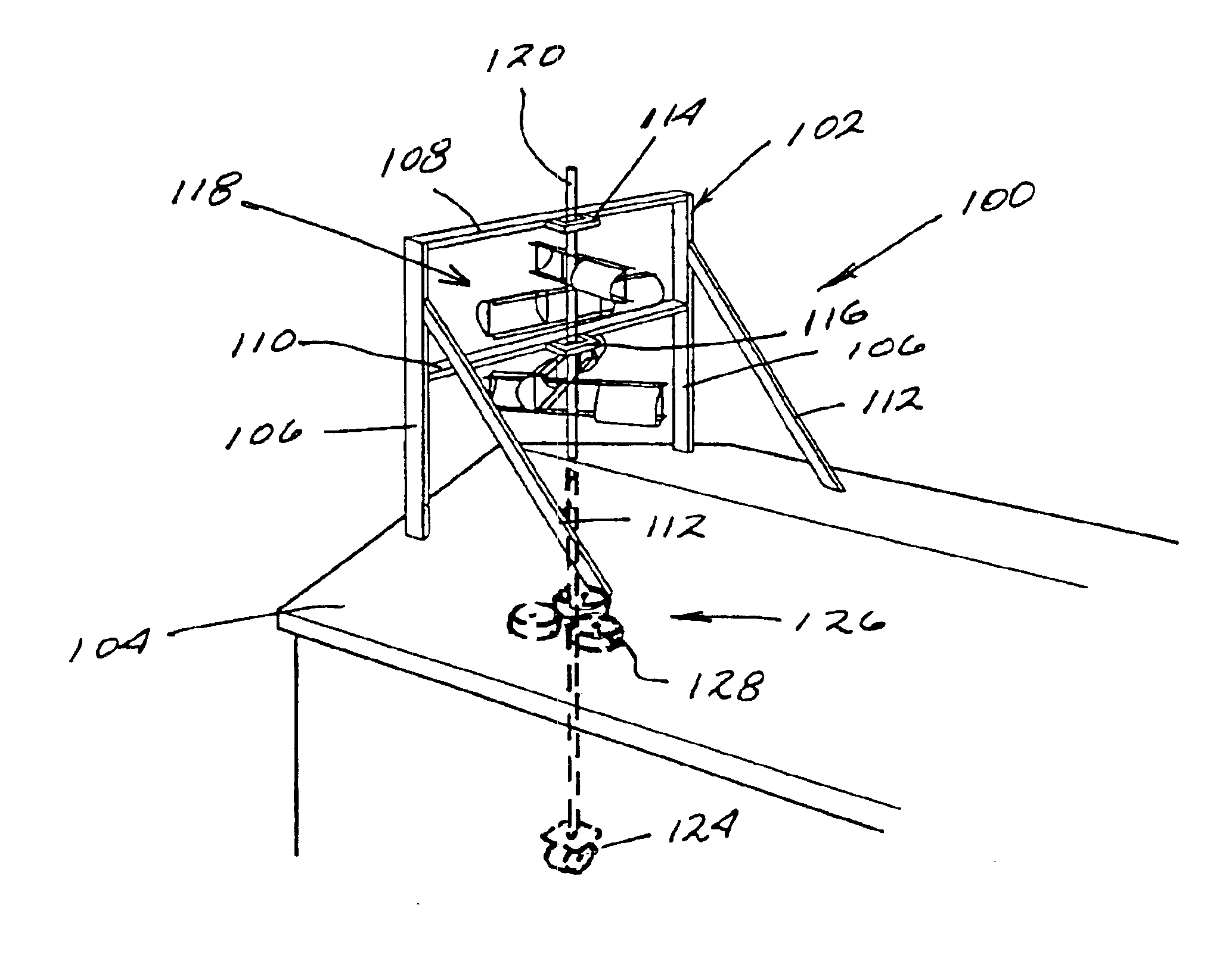
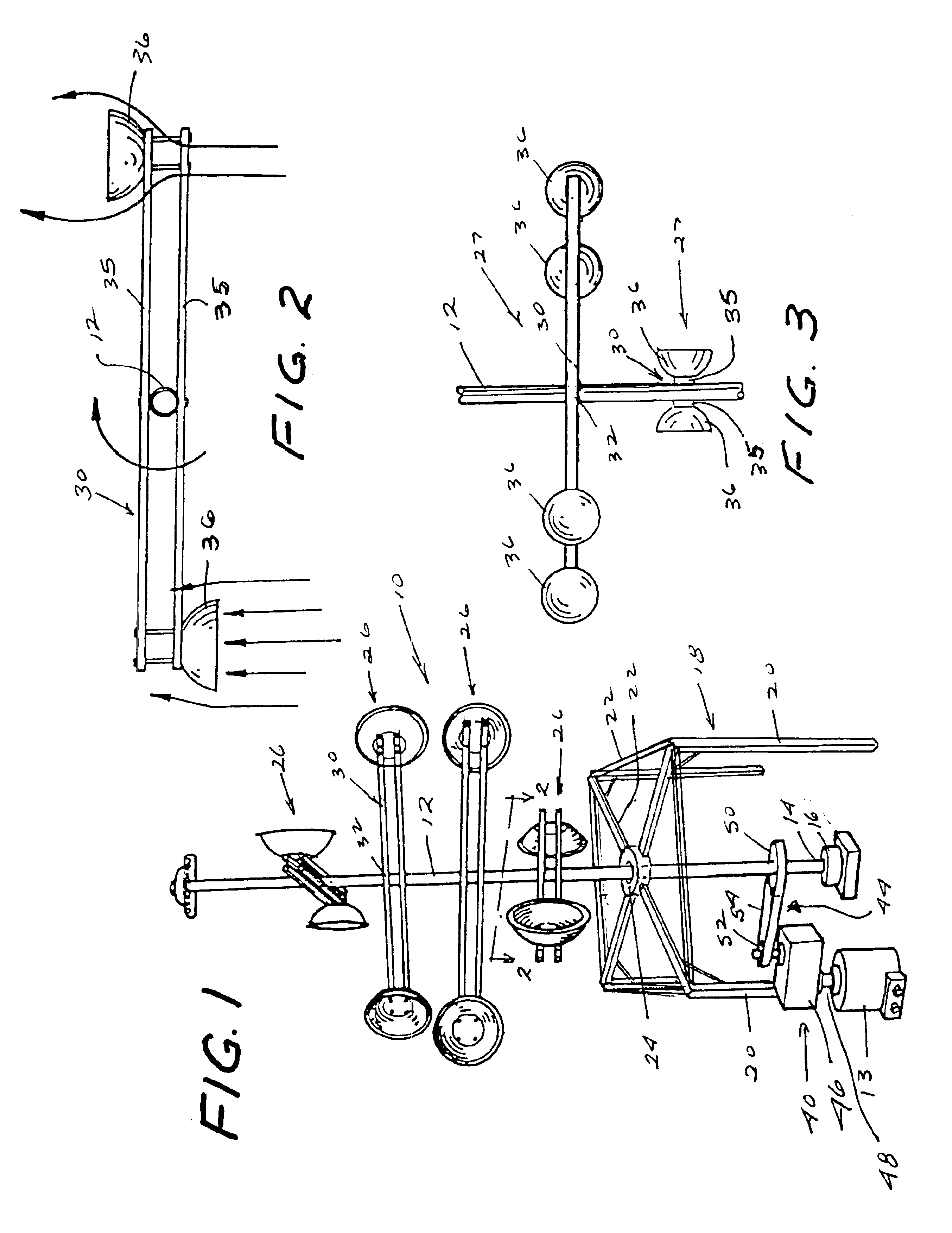
[0022]Referring to the drawings, a horizontal wind generator 10, shown schematically in FIG. 1, comprises a horizontal wind mill 11 connected with an electrical generator 13. Horizontal windmill 11 comprises a rotatable vertical pole 12 having a base 14 supported by bearings 16. A frame 18 comprising legs 20 and crossbars 22 supports the pole at an elevated position by means of suitable bearings 24 or the like that engage the pole and permit rotation thereof in the frame. The frame can take any form that provides stable support for the pole.

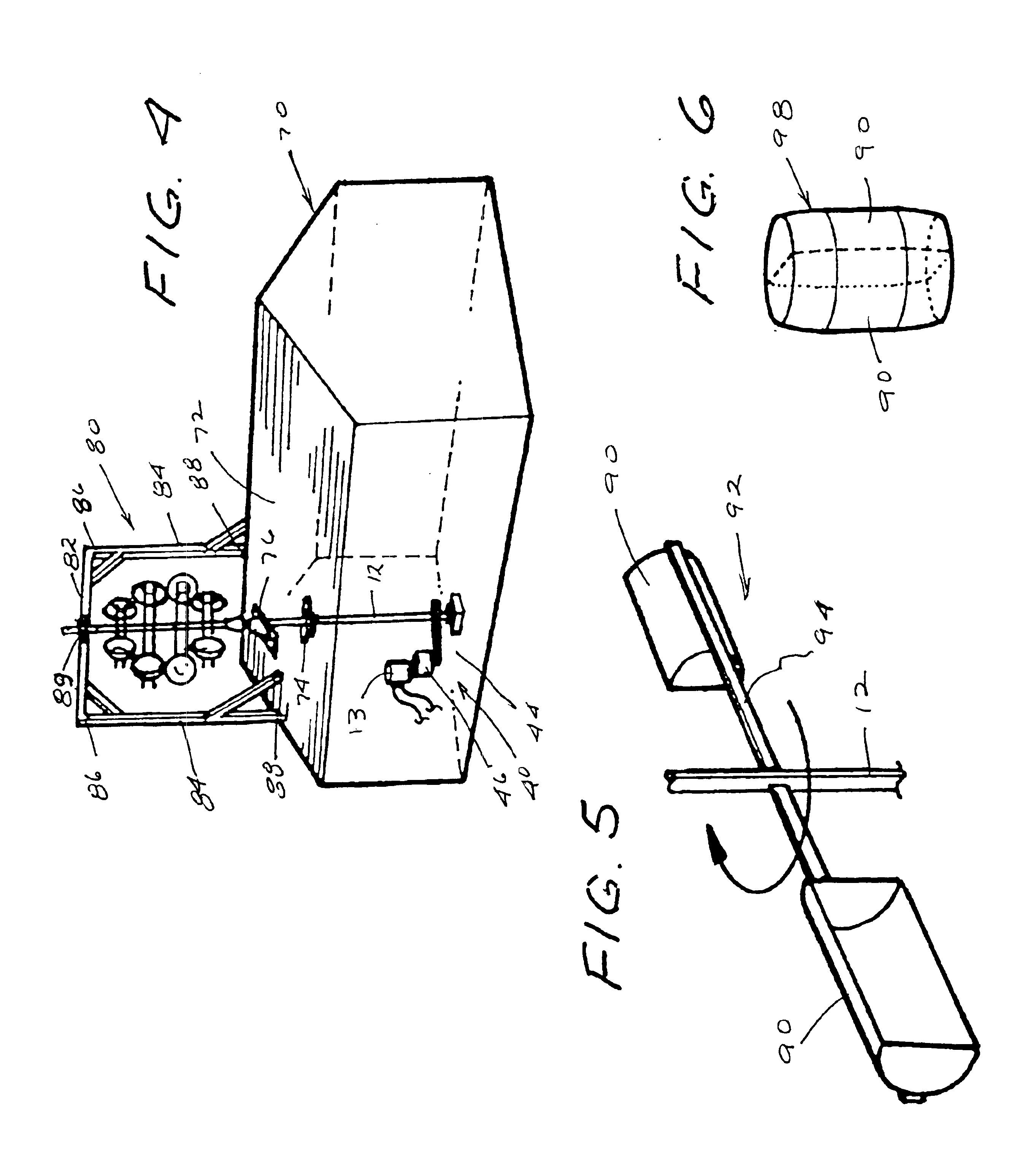
[0023]An upper portion of pole 12 is elevated to a position where it is accessible to wind forces. A plurality of horizontal wind drive units 26 are mounted at axially spaced locations along an upper portion of pole 12. The wind drive units can be identical (but do not have to be) but are angularly displaced at regular intervals about the axis of the pole (see FIG. 7). When four drive units are employed, as shown in FIG. 1, the drive units are ax...


PUM


Abstract

A horizontal wind generator comprises a horizontal windmill drivingly coupled to an electrical generator. The windmill includes a vertical drive shaft mounted for rotation in a base, with a plurality of wind drive units being mounted in wind catching positions at spaced axial locations along the drive shaft. The drive units comprise oppositely facing wind catching elements mounted on opposite sides of crossbars or frames non-rotatably attached to the pole. Multiple wind drive units are spaced along the pole and angularly displaced from adjacent units at regular intervals around the pole. Two or four spaced drive units are particularly desirable. Wind catcher elements formed of cup shaped bowls or split barrels are particularly effective and are inexpensive. The wind generator is drivingly attached to an electrical generator through a gear box and belt or chain drive mechanism. The horizontal windmill rotates the electrical generator within its desired speed range without any governor or speed control.

Description

CROSS-REFERENCES TO RELATED APPLICATIONS[0001]This is a non-provisional application based on and claiming the filing priority of abandoned provisional patent application Ser. No. 60 / 408,700, filed Sep. 6, 2002.BACKGROUND OF THE INVENTION[0002]Wind power is used for a number of purposes, including the operation of pumps and other mechanical devices and the generation of electricity. One of the more common types of wind power generators is a conventional windmill, wherein a blade or series of blades or the like rotate in a vertical plane about a horizontal axis. A problem with this type of drive mechanism is that the speed of a windmill blade increases with the speed of the wind applied to the blade. Most electrical generators operate most efficiently at a given rotational speed. Thus, such systems require a governor or other means to control the operating speed of the generator driven by the windmill. Some windmills include windmill blades where the pitch can be altered to vary the d...

Claims


Application Information

Patent Timeline
Patent Type & Authority Patents(United States)
IPC IPC(8): F03D3/02F03D3/00
CPCF03D3/02F05B2240/216Y02E10/74Y10S415/907Y02E10/728F03D9/34F03D15/10
Inventor HORJUS, THOMAS W.
Owner HORJUS THOMAS W
Why Eureka
Try Eureka