Medical instrument for milling a curved path in bone and procedure

a technology of medical instruments and curves, applied in the field of medical instruments and procedures, can solve the problems of reducing limiting the geometry that can be created, and using straight reamers to remove bone, so as to improve the loading of nearby bone, the effect of reducing the gap between implant and bon

Inactive Publication Date: 2005-09-27
DEPUY ORTHOPAEDICS INC
View PDF22 Cites 100 Cited by
  • Summary
  • Abstract
  • Description
  • Claims
  • Application Information

AI Technical Summary

Benefits of technology

[0021]The subject invention allows a user to mill bone along a predetermined curve or curved path. Milling is preferred over broaching since milling decreases the gap between implant and bone which is critical for long term fixation. The subject invention provides the ability to mill complex, curved geometry that allows better loading of the nearby bone being milled.

Problems solved by technology

A critical limitation of milling systems today is that they use straight reamers to remove bone.
Straight reamers limit the geometry that can be created in the bone and thus the external geometry of the corresponding implant.
Broaches, however, have serious limitations.
One such limitation is the risk of fracture during broaching.
Since broaching is done by pounding the broach into the bone, the bone tends to fracture.
A problem, however, with the Krause flexible shaft is that Krause is only concerned with the shaft portion and not the cutting portion of the reamer.
As well, other flexible shafts fall short for the same reasons.
Therefore, not only is the input power direction restricted, but this, in turn, restricts the angle at which the reamer may be used on a patient.

Method used


Image

  • Medical instrument for milling a curved path in bone and procedure
  • Medical instrument for milling a curved path in bone and procedure
  • Medical instrument for milling a curved path in bone and procedure

Examples


Embodiment Construction

[0036]While the invention is susceptible to various modifications and alternative forms, specific embodiments thereof have been shown by way of example in the drawings and will herein by described in detail. It should be understood, however, that there is no intent to limit the invention to the particular forms disclosed, but on the contrary, the intention is to cover all modifications, equivalents, and alternatives falling within the spirit and scope of the invention as defined by the appended claims.

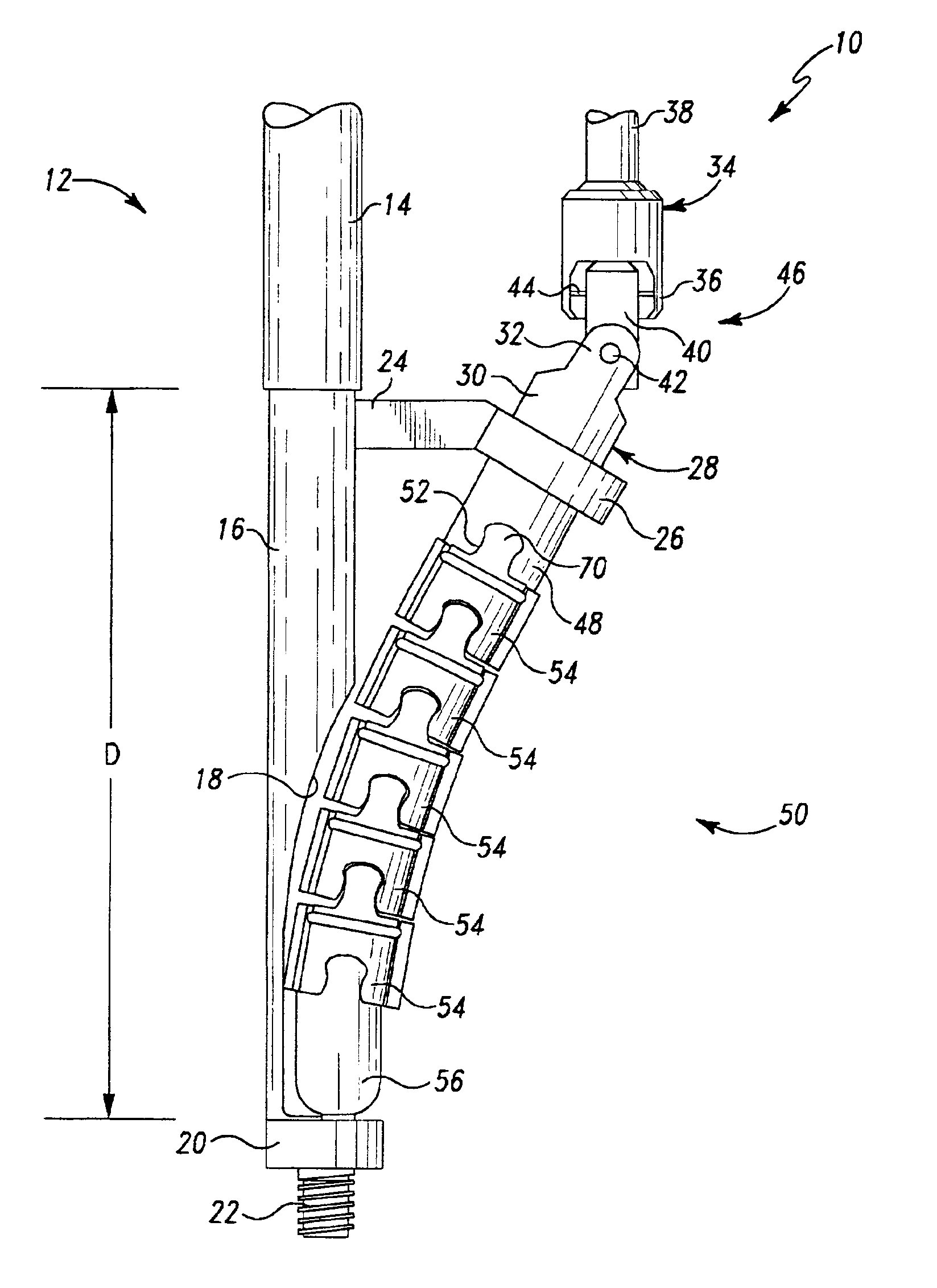
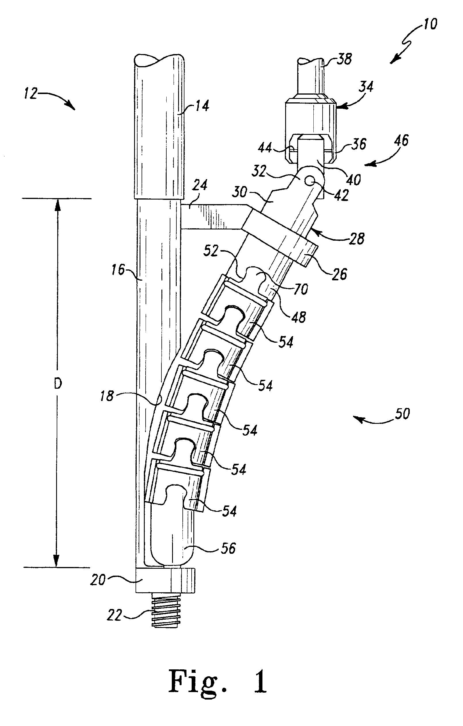
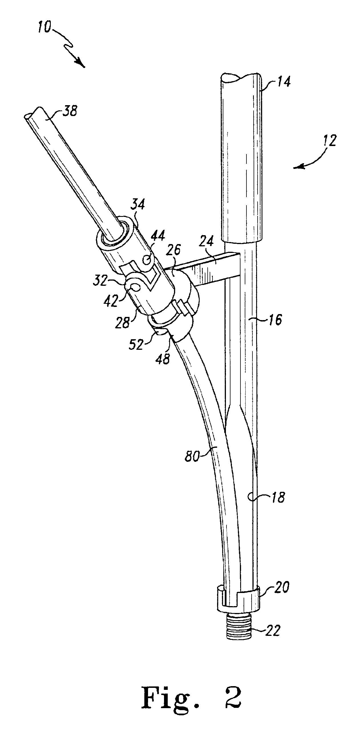
[0037]Referring now to FIG. 1 there is shown a side view of an exemplary embodiment of a bone milling apparatus generally designated 10. The bone milling apparatus 10 includes a frame, support, guide, or the like generally designated 12. The frame 12 includes a first or upper portion 14 here constituting a tube, shaft, tubular member, rod, or the like, and a second or lower portion 16 here constituting a tube, shaft, tubular member, rod, or the like, that may be smaller in diameter tha...


PUM


Abstract

A medical instrument and procedure is adapted to mill bone along a curve and with respect to at least two angles of orientation with respect to an input source of rotary motion. Particularly, the medical instrument is a bone milling apparatus that is configured to mill bone along a predetermined curved path or curve. The bone milling apparatus includes a reamer that is rotatable about a curved shaft which is retained by a frame. The shaft has a predetermined curve that corresponds to a desired milling curve. The reamer is comprised of a plurality of interconnected segments, with each segment having cutting surfaces such that each segment is a cutter. The reamer is thus flexible with respect to the interconnection between the individual segments.

Description

TECHNICAL FIELD OF THE INVENTION[0001]The present invention relates to medical instruments and procedures and, more particularly, to a medical instrument capable of milling bone along a curve, especially in preparation for implantation of a prosthesis.BACKGROUND OF THE INVENTION[0002]For implantation of prosthetic stems, such as hip stems, accurate preparation of the bone or intramedullary canal is extremely important in order to guarantee good contact between the prosthesis stem and the bone. Preparation of the bone canal for implantation of a prosthetic stem is presently prepared by drilling a resected end of a bone, such as a femur, and then preparing an area adjacent the drilled hole to provide a seat for the prosthetic stem.[0003]Preparation of the area adjacent the drilled hole may be accomplished by broaching or by milling. Currently, however, milling has been identified as an extremely precise method of bone preparation in many orthopaedic applications as compared to broachi...

Claims


Application Information

Patent Timeline
Patent Type & Authority Patents(United States)
IPC IPC(8): A61B17/16A61B17/56
CPCA61B17/1668A61B17/1631A61B17/164
Inventor MCCLEARY, LARRY G.DWYER, KIMBERLY A.
Owner DEPUY ORTHOPAEDICS INC
Why Eureka
Try Eureka