
Leak proof pressure relief valve for secondary batteries

a pressure relief valve and secondary battery technology, applied in the field of secondary batteries, can solve the problems of secondary battery being subjected to rapid charge, battery being subjected to overcharge conditions, and secondary battery being subjected to discharge conditions that range from very gentle to abusiv

Inactive Publication Date: 2005-09-27
ZINCFIVE POWER INC
View PDF2 Cites 24 Cited by
  • Summary
  • Abstract
  • Description
  • Claims
  • Application Information

AI Technical Summary

Problems solved by technology

Quite often a secondary battery may be subjected to rapid charge, and depending on the nature of the charging equipment and its control circuits, a battery may be subjected to overcharge conditions.
Likewise, a secondary battery may be subjected to discharge conditions that range from very gentle to abusive—for example, if the secondary battery is driving an electric motor that stalls.
However, typically spring loaded relief valves operate at a higher pressure then Bunsen Valves, so that typically they may be activated only when the cell or battery is operating under abusive conditions.
However, especially in the conditions or circumstances where a battery is operated in an inverted position—accidentally or deliberately—Bunsen Valves in particular can fail, or they can encounter operating difficulties and problems.
Such circumstances can be damaging to any electronic components that are powered by the battery.
Also, and in any event, the physical presence of electrolyte between the rubber relief valve structure and the sealing surface against which it operates, in a typical Bunsen Valve, may prevent proper function in the future.
In the event of an alkaline electrolyte being present in the region of the pressure relief valve vent structure, that circumstance can be disastrous.
Alkaline electrolyte tends to have a low surface tension, and therefore is much more likely to creep or enter the valve mechanism if the battery is in an inverted condition.

Method used


Image

  • Leak proof pressure relief valve for secondary batteries
  • Leak proof pressure relief valve for secondary batteries

Examples


Embodiment Construction

[0035]The novel features which are believed to be characteristic of the present invention, as to its structure, organization, use and method of operation, together with further objectives and advantages thereof, will be better understood from the following discussion.

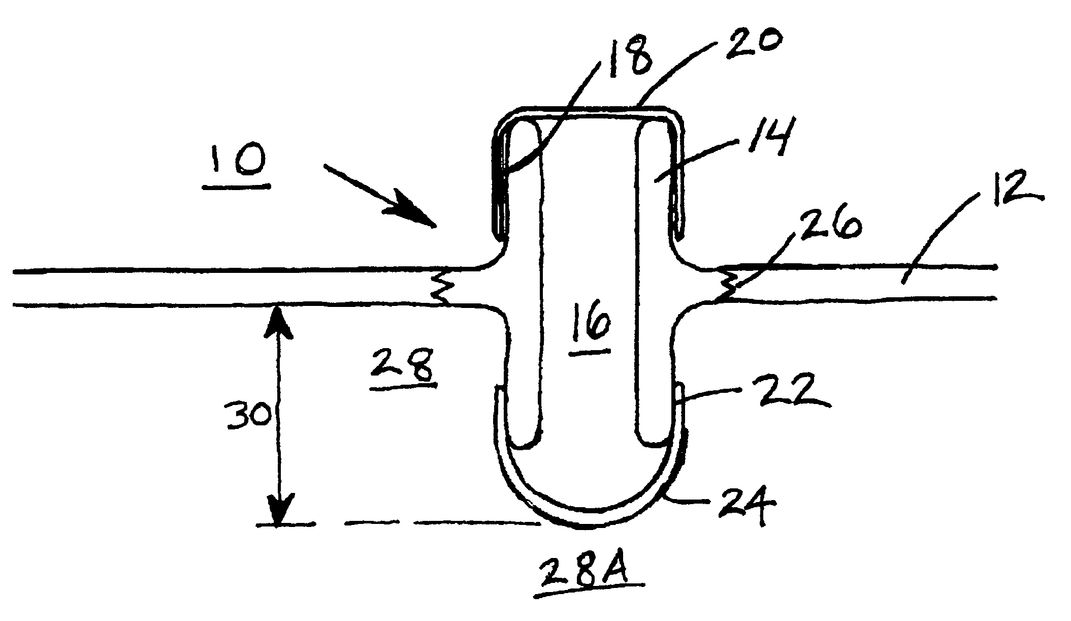
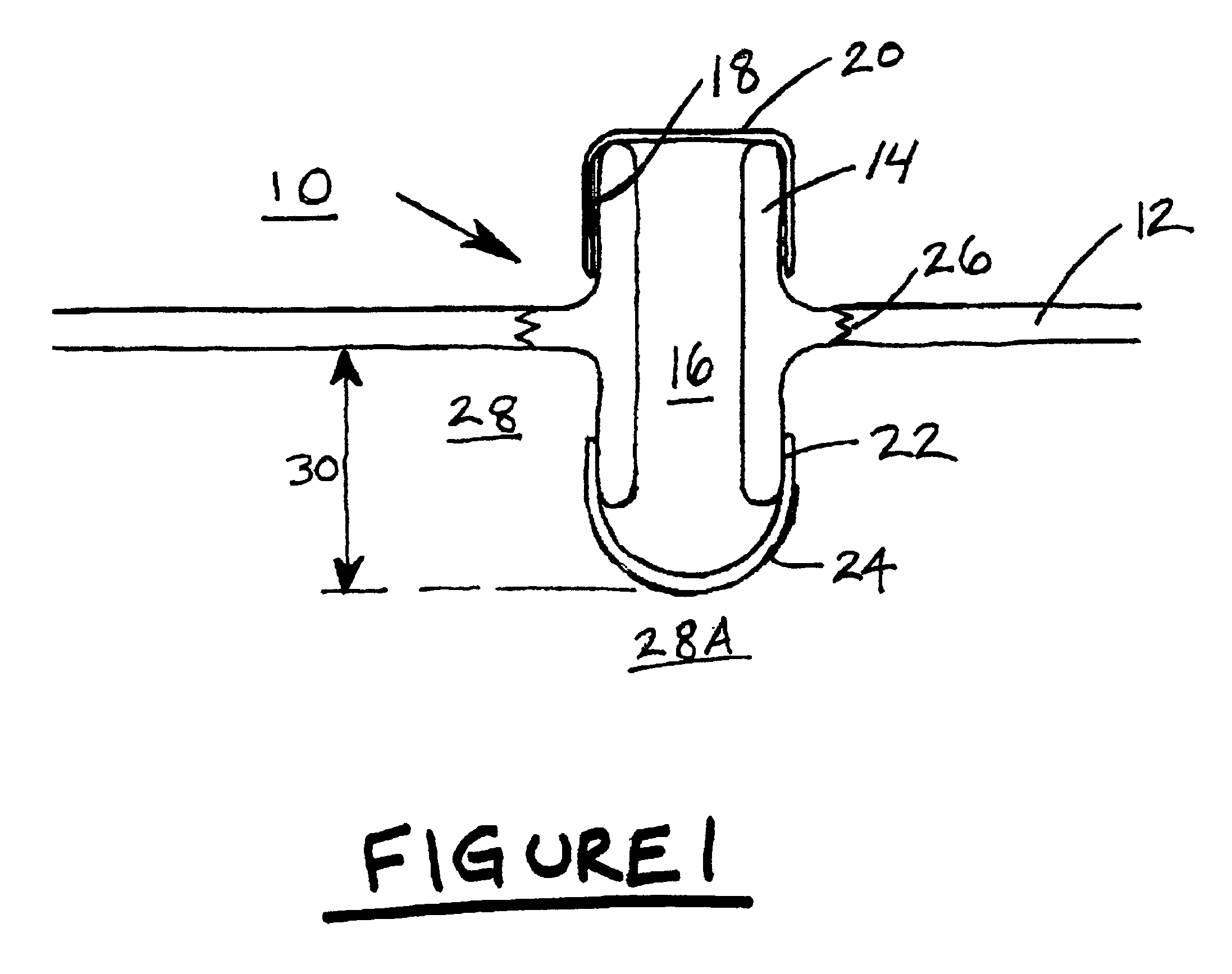
[0036]The pressure relief valve structure of the present invention is shown generally at 10 in FIG. 1. The structure comprises a wall structure 14—usually, cylindrical—which defines a gas flow chamber 16. The pressure relief valve structure 10 is installed in a top surface 12 of the a battery case, the remaining details of which are not important to the present discussion.

[0037]At the upper end of the gas flow chamber 16, an outer relief vent 18 is placed. The structure of the outer relief vent 18, and a protective impervious plastic cap 20 which is placed thereover, is effectively that of a typical Bunsen-type pressure relief vent or check valve structure.

[0038]At the bottom end of the gas flow chamber 16, which extend...


PUM

PropertyMeasurementUnit
pressuresaaaaaaaaaa
pressureaaaaaaaaaa
volumeaaaaaaaaaa

Abstract

Secondary batteries are subjected to power cycling, and those which have a liquid electrolyte within the interior volume are equipped with a pressure relief valve. A void space over the liquid electrolyte may be subjected to gas pressure variations with respect to the ambient. The pressure relief valve structure comprises a vertically oriented gas flow chamber, and an outer relief vent adapted to open only when gas pressure within the battery and the gas flow chamber exceeds a predetermined pressure with respect to the ambient pressure. The gas flow chamber extends below the top surface of the battery, and has a dome-like cap which extends downwardly and has a plurality of openings so as to permit unimpeded gas flow between the interior of the battery and the gas flow chamber. There is a porous membrane covering the dome which permits gas flow between the interior of the battery and the gas flow chamber, but precludes flow of liquid electrolyte from the interior volume of the battery to the gas flow chamber.

Description

[0001]This application claims the benefit of Provisional Application No. 60 / 276,364, filed Mar. 15, 2001.FIELD OF THE INVENTION[0002]This invention relates to secondary batteries, and particularly to a leak proof pressure relief valve for use in secondary batteries.BACKGROUND OF THE INVENTION[0003]Secondary batteries may be subjected to a variety of different circumstances surrounding their charge and discharge. Quite often a secondary battery may be subjected to rapid charge, and depending on the nature of the charging equipment and its control circuits, a battery may be subjected to overcharge conditions.[0004]Likewise, a secondary battery may be subjected to discharge conditions that range from very gentle to abusive—for example, if the secondary battery is driving an electric motor that stalls.[0005]Under any or all of those conditions, the chemistry of the battery—whether it be a lead acid battery, for example, or an alkaline battery—may be such that the interior volume of the ...

Claims


Application Information

Patent Timeline
Patent Type & Authority Patents(United States)
IPC IPC(8): H01M2/12H01M10/52
CPCH01M2/1229H01M2/1294H01M50/325H01M50/342Y02E60/10
Inventor PHILLIPS, JEFFREY
Owner ZINCFIVE POWER INC
Learn More