Planer apparatus

a technology of planer and cutter head, which is applied in the direction of flat surface machines, precision positioning equipment, manufacturing tools, etc., can solve the problems of affecting the accuracy of the planer, and placing undesirable torque on the cutterhead, etc., to achieve the effect of convenient and convenient use, convenient and convenient installation, and convenient adjustmen

Inactive Publication Date: 2005-10-04
CHANG TYPE INDAL
View PDF48 Cites 10 Cited by
  • Summary
  • Abstract
  • Description
  • Claims
  • Application Information

AI Technical Summary

Benefits of technology

[0013]Another embodiment of the invention includes a planer having a base, a top frame connected to the base, a cutterhead movably supported relative to the base to define an adjustable opening therebetween for selective travel in a first direction toward the base and a second opposite direction, and a depth stop mechanism attached to the top frame and not extending into the adjustable opening. The depth stop mechanism selectively prevents travel of the cutterhead in the first direction beyond a pre-selected distance from the base.
[0019]It is a feature of at least one embodiment of the invention to provide a compact depth stop mechanism for a full range of travel of the cutterhead of a planer or other similar machine.
[0020]Another feature of the invention is to provide efficient, effective and easily installable accessories for a portable planer and other similar machines.
[0021]It is also feature of at least one embodiment of the invention to provide an inexpensive and readily adaptable depth measuring device and a convenient workpiece level indicator, either of which that can be used with or without a depth stop mechanism for a planer or other similar machine.
[0023]It is also a feature of at least one embodiment of the invention to provide a dust removal assembly that is readily attached to and detached from a portable planer.

Problems solved by technology

U.S. Pat. No. 6,089,287 to Welsh et al. discloses a planer with a depth stop adjustment mechanism that allows an operator to select a minimum workpiece depth from one or more predetermined depths, but does not allow selection of any depth within the full range of travel of the cutterhead of the planer.
Also current depth stop arrangements are located between the cutterhead and the workpiece support table and can place undesirable torque on the cutterhead if the cutterhead is inadvertently lowered beyond the point wherein the depth stop engages the table or other support structure.
Such torque can result in damage to the apparatus for positioning the cutterhead.

Method used


Image

  • Planer apparatus
  • Planer apparatus
  • Planer apparatus

Examples


Embodiment Construction

[0046]Referring now to the drawings for the purpose of illustrating the invention and not for the purpose of limiting the same, it is to be understood that standard components or features that are within the purview of an artisan of ordinary skill and do not contribute to the understanding of the various embodiments of the invention are omitted from the drawings to enhance clarity, even when such features may otherwise be necessary for the operation of a machine, such as a planer, embodying the invention. In addition, it will be appreciated that the characterizations of various components described herein as moving, for example, upwardly or downwardly, or being vertical or horizontal, are relative characterizations only based upon the particular position or orientation of a given component for a particular application.

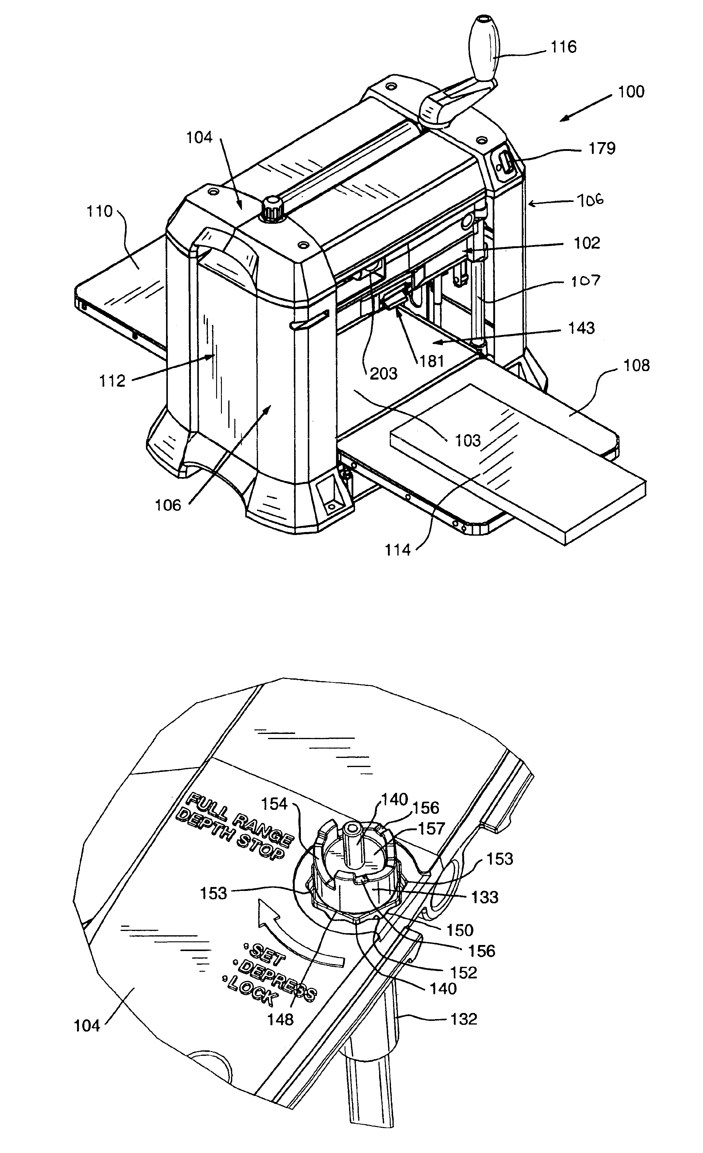
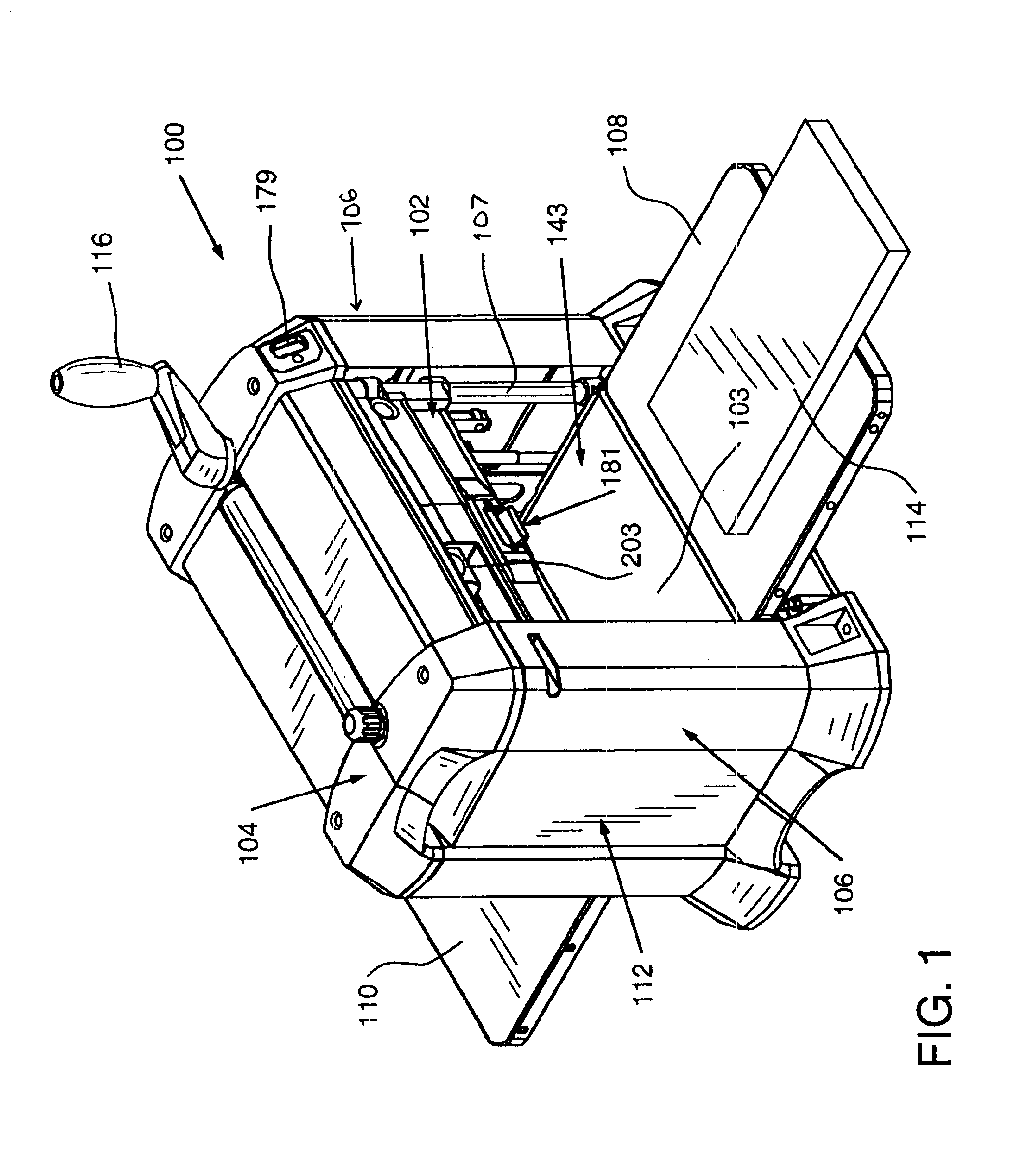
[0047]FIG. 1 is an isometric view of a portable planer 100 according to one embodiment of the invention. The planer 100 includes a support structure, generally designa...


PUM

PropertyMeasurementUnit
distanceaaaaaaaaaa
depthaaaaaaaaaa
rotationaaaaaaaaaa

Abstract

A planer having a base, a first support member attached to the base and supporting a cutterhead for selective travel in a first direction toward the base and a second opposite direction, a top frame attached to the first support member and a depth stop mechanism attached to the top frame for selectively preventing travel of the cutterhead in the first direction beyond a pre-selected distance from the base. A depth measuring device including a retractable tape may be attached to the cutterhead. A workpiece level indicator plate movable between an engaged position and a disengaged position may be attached to the planer to indicate contact with a workpiece. A locking mechanism for locking a pivotable infeed table of a planer in the upright position for storage, and thereby switching off power to the planer is also disclosed. The planer may include a readily attachable and detachable dust removal assembly.

Description

BACKGROUND OF THE INVENTION[0001]1. Field of the Invention[0002]The invention relates to a planer apparatus and, in particular, to a depth stop mechanism and other accessories for a planer.[0003]2. Description of the Invention Background[0004]Over the years, in response to consumer demand, thickness and finishing planers, i.e. planers for reducing the thickness of a piece of wood or similar materials while providing a smooth and flat finish, have been decreasing in size. Such portable planers balance the need to provide the required power to produce a smooth finish with the need to conserve space and decrease weight for portability.[0005]The popularity of portable planers among professionals and woodworking enthusiasts has spurred the introduction of new features designed to increase versatility, precision and convenience. For example, U.S. patent application Ser. No. 09 / 782,453 to Garcia et al., assigned to the assignee of the present invention, discloses a portable planer having a...

Claims


Application Information

Patent Timeline
Patent Type & Authority Patents(United States)
IPC IPC(8): B23Q16/00B27C1/00B27C1/14B27C1/04
CPCB23Q16/001B27C1/04B27C1/14Y10T409/308176Y10T409/304088Y10T409/308064Y10T83/202
Inventor GARCIA, JAIME E.MCNEAL, JR., WAYMON L.ROE, VANCE E.WESTON, JEFFREY D.
Owner CHANG TYPE INDAL
Why Eureka
Try Eureka