Fan cover heat dissipation assembly for a host computer CPU

a technology for a host computer and a heat dissipation assembly, which is applied in the direction of machines/engines, liquid fuel engines, instruments, etc., can solve the problems of system instability and computer crash, and achieve the effect of affecting the efficiency of heat dissipation and the effect of high temperature heat dissipation

Inactive Publication Date: 2005-10-04
HUNG KUO CHUAN
View PDF4 Cites 27 Cited by
  • Summary
  • Abstract
  • Description
  • Claims
  • Application Information

AI Technical Summary

Benefits of technology

[0006]A primary objective of the present invention is to provide the fan cover heat dissipation assembly for a host computer CPU that realizes effectiveness of high temperature heat dissipation.
[0008]According to aforementioned structural configuration, the wind tunnel appropriately covers the heat dissipation fins configured atop the CPU. Hot air of the CPU is first evenly dissipated towards the heat dissipation fins atop the CPU, and the hot air of the heat dissipation fins is amassed within the fan cover, thereafter the fans configured at a rear-end within the fan cover expel the hot air outwards from the computer case by means of drawing in, drawing out and discharging of such, thereby achieving effectiveness of high temperature heat dissipation. Such a configuration thereby prevents turbulent flow from generating within the computer case, and affecting efficiency of heat dissipation therein, subsequently resulting in problems of system instability and crashing of computer thereof.

Problems solved by technology

Such a configuration thereby prevents turbulent flow from generating within the computer case, and affecting efficiency of heat dissipation therein, subsequently resulting in problems of system instability and crashing of computer thereof.

Method used


Image

  • Fan cover heat dissipation assembly for a host computer CPU
  • Fan cover heat dissipation assembly for a host computer CPU
  • Fan cover heat dissipation assembly for a host computer CPU

Examples


Embodiment Construction

[0015]A detailed description of structure, devices and characteristics of a practicable preferred embodiment of the present invention in accompaniment with drawings is disclosed hereinafter:

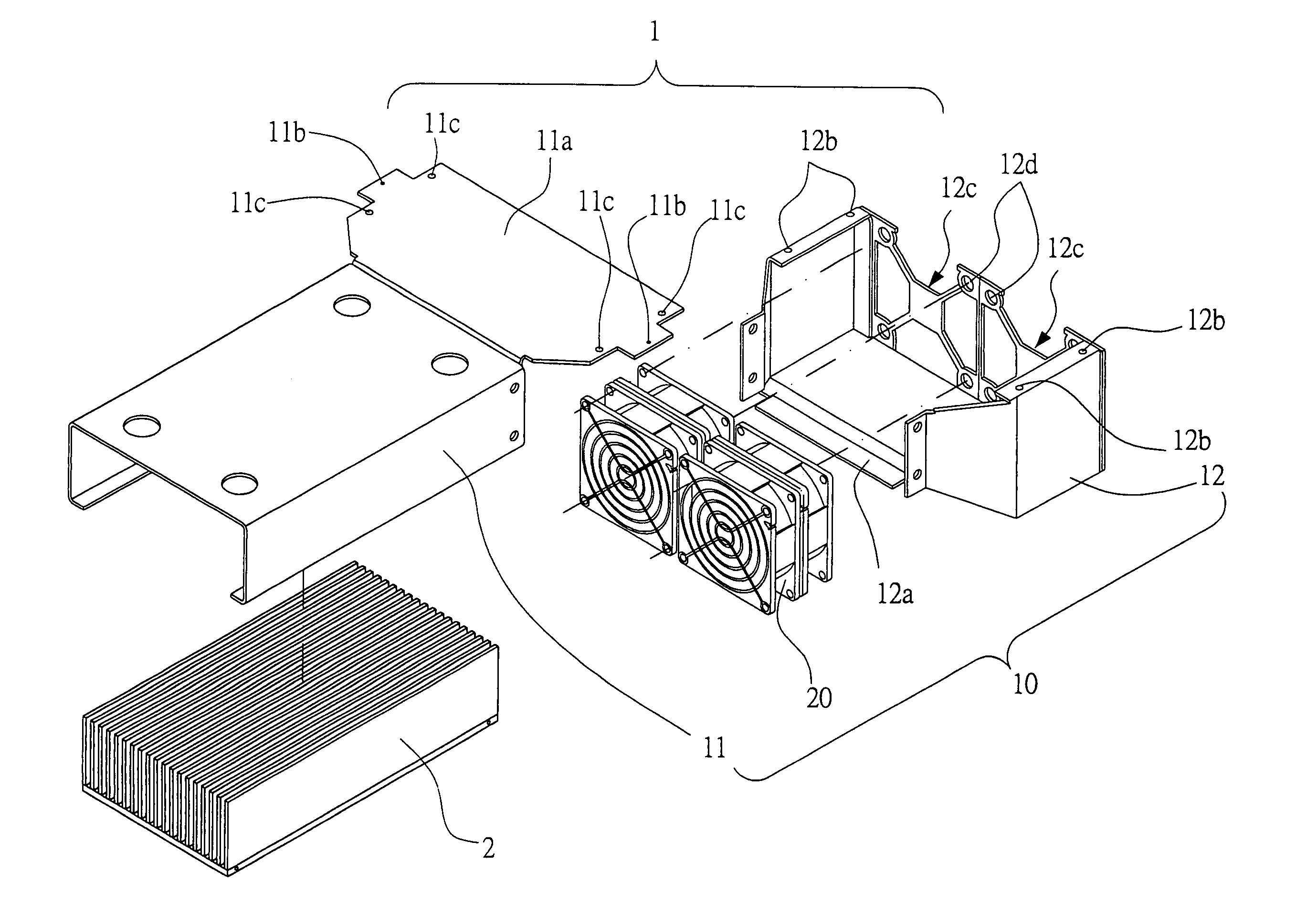
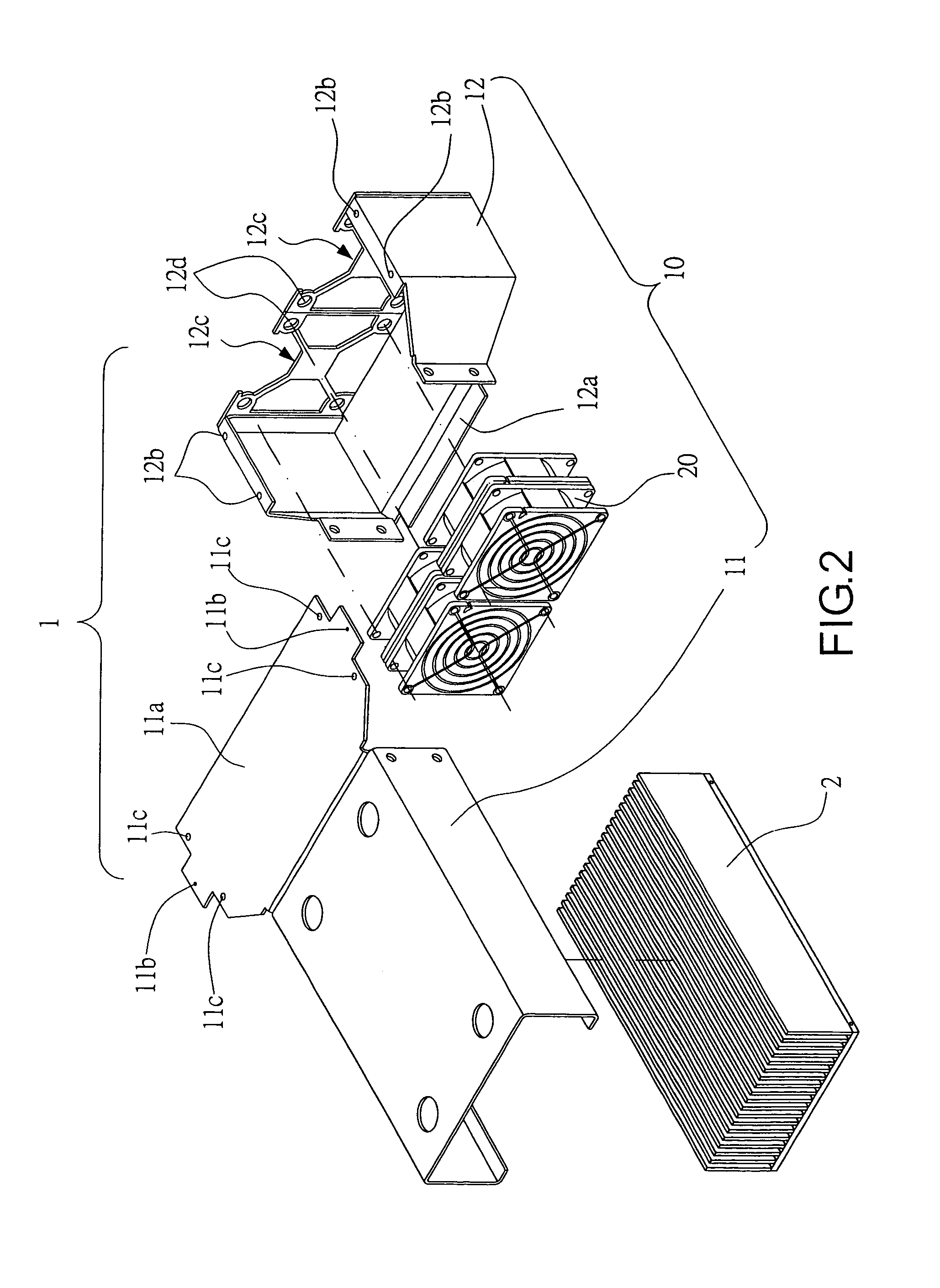
[0016]Referring to FIGS. 2, 3, and 4, which show a fan cover heat dissipation assembly for a host computer CPU of the present invention, primarily comprising and so structured to include a fan cover body 10 and two fans 20. Wherein:

[0017]The fan cover body 10 is constructed to include a wind tunnel cover 11 configured at a front-end and a fan cover 12 configured at a rear-end. Wherein a small section of a bottom edge of two perpendicular plates of the wind tunnel cover 11 are inwardly bent, thereby making width of an opening of a lower portion of the wind tunnel cover 11 slightly larger than that of heat dissipation fins 2. A rear-end of the wind tunnel cover 11 is provided with a backwardly extended fan top cover 11a. Left and right sides of the fan top cover 11a are provided with screw holes 11...


PUM


Abstract

A fan cover assembly installed within a computer case of a host computer, thereby providing a heat dissipating effect of for a CPU (central processing unit). Configured for usage in a slim IU industrial server computer case, whereby the fan cover assembly is structured to comprise a fan cover body and fans installed therein. Wherein the fan cover body is constructed to include a wind tunnel cover configured at a front-end and a fan cover configured at a rear-end thereof. Width and height of the wind tunnel cover are established so as to correspond with width and height of the CPU with addition of heat dissipation fins configured atop thereof. Upon assembling the fan cover body, and tightly screwing down such onto a back panel of the computer case, the fans expel hot air outwards, thereby achieving effectiveness of high temperature (60° C. and above) heat dissipation.

Description

BACKGROUND OF THE INVENTION[0001](a) Field of the Invention[0002]The present invention relates to a fan cover heat dissipation assembly for a host computer CPU, and more particularly to a fan cover heat dissipation assembly configured for usage in an IU slim industrial server computer case, thereby providing functionality to strengthen heat dissipation of the CPU when such reaches a high temperature (60° C. and above), and constructed to include structural components comprising a fan cover body and a fan.[0003](b) Description of the Prior Art[0004]Accordingly, a CPU utilized by a conventional industrial server generally consumes high electric power, and thus hot air generated by the CPU is comparatively large. However, space reserved for heat dissipation within a computer case is limited. Because a conventional heat sink is utilized in computer cases of every kind, and therefore the heat sink is employed as a heat dissipation configuration in majority of computer cases. Consequently...

Claims


Application Information

Patent Timeline
Patent Type & Authority Patents(United States)
IPC IPC(8): F03B11/00F04D25/16F04D29/58G06F1/20H05K7/20
CPCF04D25/166F04D29/582G06F1/20H05K7/20172H05K7/20727
Inventor HUNG, KUO-CHUAN
Owner HUNG KUO CHUAN
Why Eureka
Try Eureka