Eureka AIR delivers breakthrough ideas for toughest innovation challenges, trusted by R&D personnel around the world.

Putter-heads

Inactive Publication Date: 2005-10-04
LINDSAY LTD
View PDF23 Cites 18 Cited by
  • Summary
  • Abstract
  • Description
  • Claims
  • Application Information

AI Technical Summary

Benefits of technology

[0012]The location of attachment of the putter-shaft to the putter-head has been found to have a significant effect on putting characteristics of the head. In particular, ratios d1/K and d2/K, relating respectively the horizontal offset d1 millimeters of the attachment from the said heel-toe axis, and its vertical offset d2 millimeters above that axis, to the radius of gyration K, are relevant. Either or, desir

Problems solved by technology

With this head function G=575, which provides moderate dS / dh, but the high hc combined with positive loft results in backspin increasing significantly with low impact-height and this in turn results in (the predicted) loss of distance at low impact height.

Method used


Image

  • Putter-heads
  • Putter-heads
  • Putter-heads

Examples


Embodiment Construction

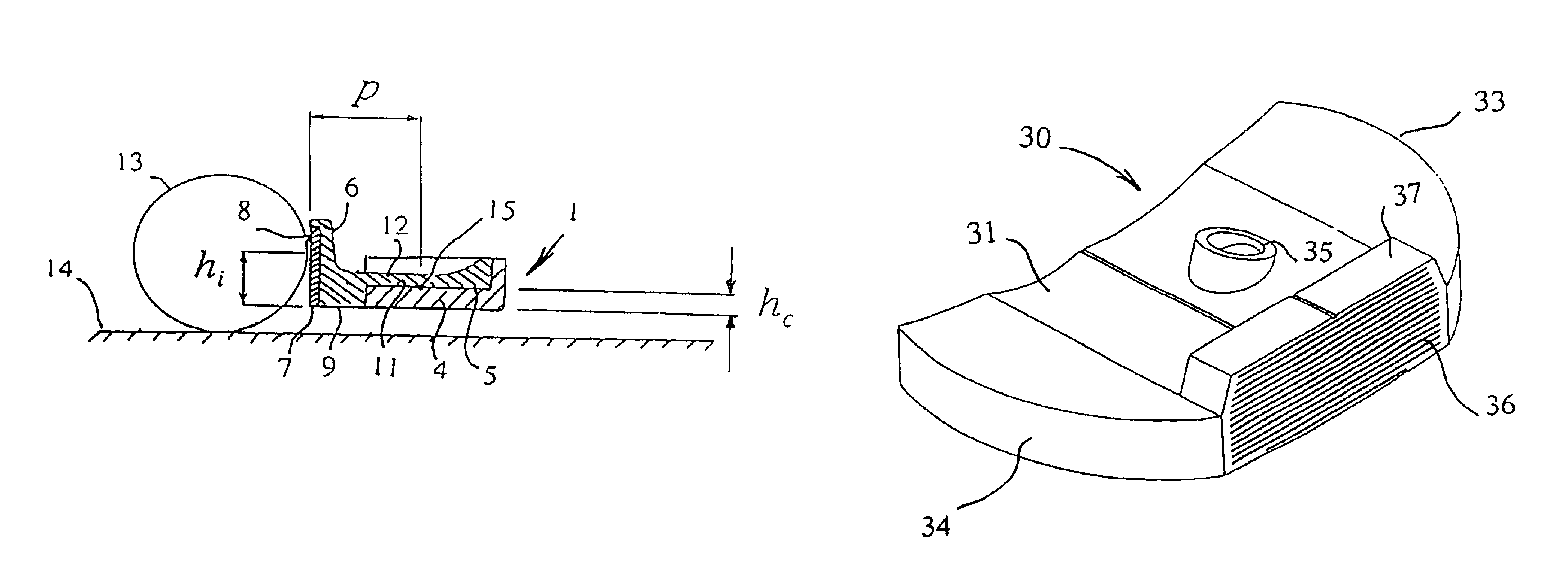
[0025]Referring to FIGS. 1 and 2, the putter-head 1, which is attached near its heel 2 to a putter-shaft 3, comprises a substantially flat-topped base 4, a bumper 5 bonded firmly to the base 4 and having an upstanding forward flange 6, and an element 7 that is inset in, and bonded to, the front of the flange 6 to provide the impact-face 8 of the head 1. The base 4 extends the length of the head 1 with a curved bottom or sole 9, to define the toe 10 of the head 1 as well as its heel 2.

[0026]In practice there may be departure from the somewhat strictly-rectangular configuration shown for the base 4, to incorporate stylistic features, angled surfaces and rounded edges. In order to conform to the Rules of Golf, the putter head of FIGS. 1 and 2 should have only one surface, namely impact-face 8, that can be used as an impact-face; the opposite, rear face and the toe and heel ends should thus contain features which prevent them from being usable in this regard.

[0027]As shown most clearly ...


PUM


Abstract

A putter-head (1) has its center of mass (15) spaced p mm behind its impact-face (8) at a height hc mm above the head-bottom (9), a loft angle α12 at height 12 mm above the head-bottom (9), a moment of inertia / kg-mm2 about the vertical axis through the center of mass (15), a mass M kg and a radius of gyration of K mm about the heel-toe axis (2-10) of the head through the center of mass (15), where p / l is not more than 0.18, hc is less than [12−p×sin(α12)], and a parameter G=[p+(3.2+70×M)×K2 / p] is less than 350. The ratio d2 / K is less than 1.0, d2 mm being the vertical offset above the heel-toe axis (2-10) of the axis of attachment of the putter-shaft (3) to the putter-head (1); the attachment-axis of the shaft may be spaced by no more than the shaft-radius from the center of mass. The impact-face (36) may have an upper flat section (38) that merges smoothly into a cylindrical lower section (39), and the head (30) may be constructed with a high-density part (32;40) that extend lengthwise of the heel-toe axis and is either bonded to the underside of a lower-density part (31), or forms both an upstanding front flange (43) and a rear body-section (41) of larger mass than, and spaced from, the flange (43).

Description

[0001]This application is a national stage completion of PCT / GB02 / 03995 filed Sep. 2, 2002 which claims priority from British Application Serial No. 0210581.5 filed May 9, 2002, British Application Serial No. 0209060.3 filed Apr. 20. 2002, British Application Serial No. 0205962.4 filed Mar. 14, 2002, British Application Serial No. 0130838.6 filed Dec. 22, 2001, and British Application Serial No. 0121261.2 filed Sep. 1, 2001.FIELD OF THE INVENTION[0002]This invention relates to putter-heads.BACKGROUND OF THE INVENTION[0003]In putting a golf ball, it is desirable to impart forward rolling spin or topspin to the ball during the putting stroke. Topspin reduces ball skid on the putting surface and helps to initiate pure rolling motion, and it one of the objects of the present invention to provide an improved putter-head for imparting topspin to a golf ball on impact.SUMMARY OF THE INVENTION[0004]According to the present invention there is provided a putter-head having a centre of mass lo...

Claims


Application Information

Patent Timeline
IPC IPC(8): A63B53/02A63B53/04
CPCA63B53/02A63B53/0487A63B2053/0441A63B2053/0433A63B2053/0491A63B2053/0416A63B53/0441A63B53/0416A63B53/0433A63B60/00
Inventor LINDSAY, NORMAN MATHESON
Owner LINDSAY LTD
Why Eureka
Eureka Blog
Learn More