
Covering structure for swimming pools

Inactive Publication Date: 2005-10-11
LEURENT GHISLAIN HENRI
View PDF19 Cites 23 Cited by
  • Summary
  • Abstract
  • Description
  • Claims
  • Application Information

AI Technical Summary

Benefits of technology

[0011]The purpose of the present invention then is to redress these shortcomings by proposing a means of preventing the occurrence of such scratch marks, which means, moreover, will facilitate the maneuvering of lateral-wall panels along their guide grooves.
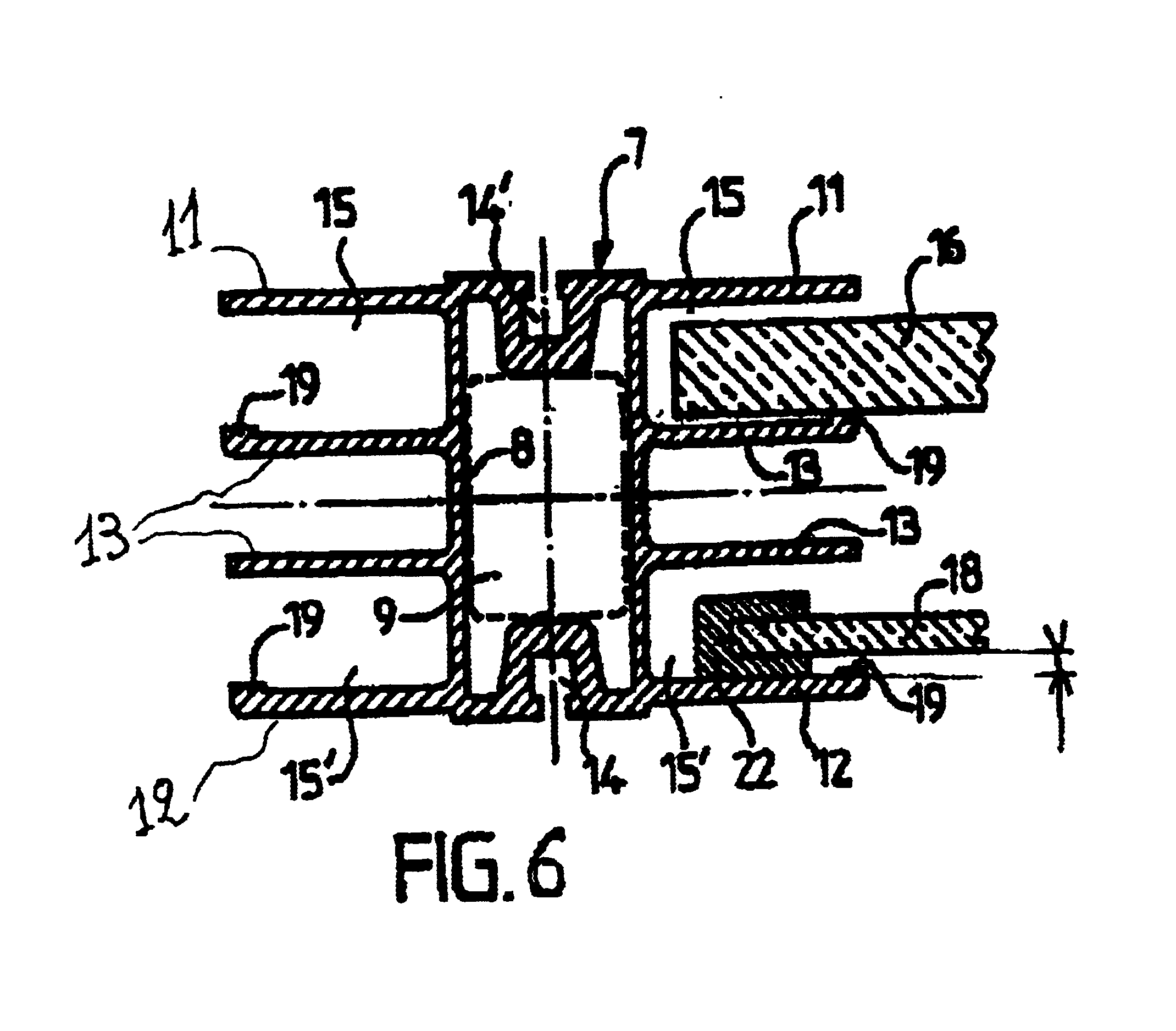
[0015]Obviously, the overall thickness of the protective and elevating borders, which are always affixed to and an integral part of the maneuverable panels, shall be less than the height of the opening of the guide grooves of the profile of the arch receiving said panels so that the edges of the panels may be easily inserted, laterally, between each pair of arches forming the covering structure.
[0018]It should also be noted that, depending on the type of covering structure to be assembled and the desired level of isolation, it may be beneficial to use panels of varying thickness to form the roof section of an element, and to be able to do so without having recourse to another type of profile, thereby reducing the cost of manufacturing, storing and distributing the profiles.
[0019]Consequently, the invention further provides a reversible profile that can used to form the arches of the covering structure and whose design enables it to receive roof-section panels of varying thickness, without having recourse to another type of profile.

Problems solved by technology

Consequently, the lateral edges of the panels come naturally into contact with the inner walls of the guide grooves into which they are fitted so that, with repeated maneuvering of the lateral-wall panels (raising and lowering), scratching tends to occur along the edges of the panels in contact with the supporting profiles.
From an aesthetic point of view, this constitutes a defect that is difficult for users to accept.
Additionally, on account of the friction that accompanies the movement of these lateral-wall panels in their guide grooves, maneuvering the panels requires a greater effort on the part of the user.

Method used


Image

  • Covering structure for swimming pools
  • Covering structure for swimming pools
  • Covering structure for swimming pools

Examples


Embodiment Construction

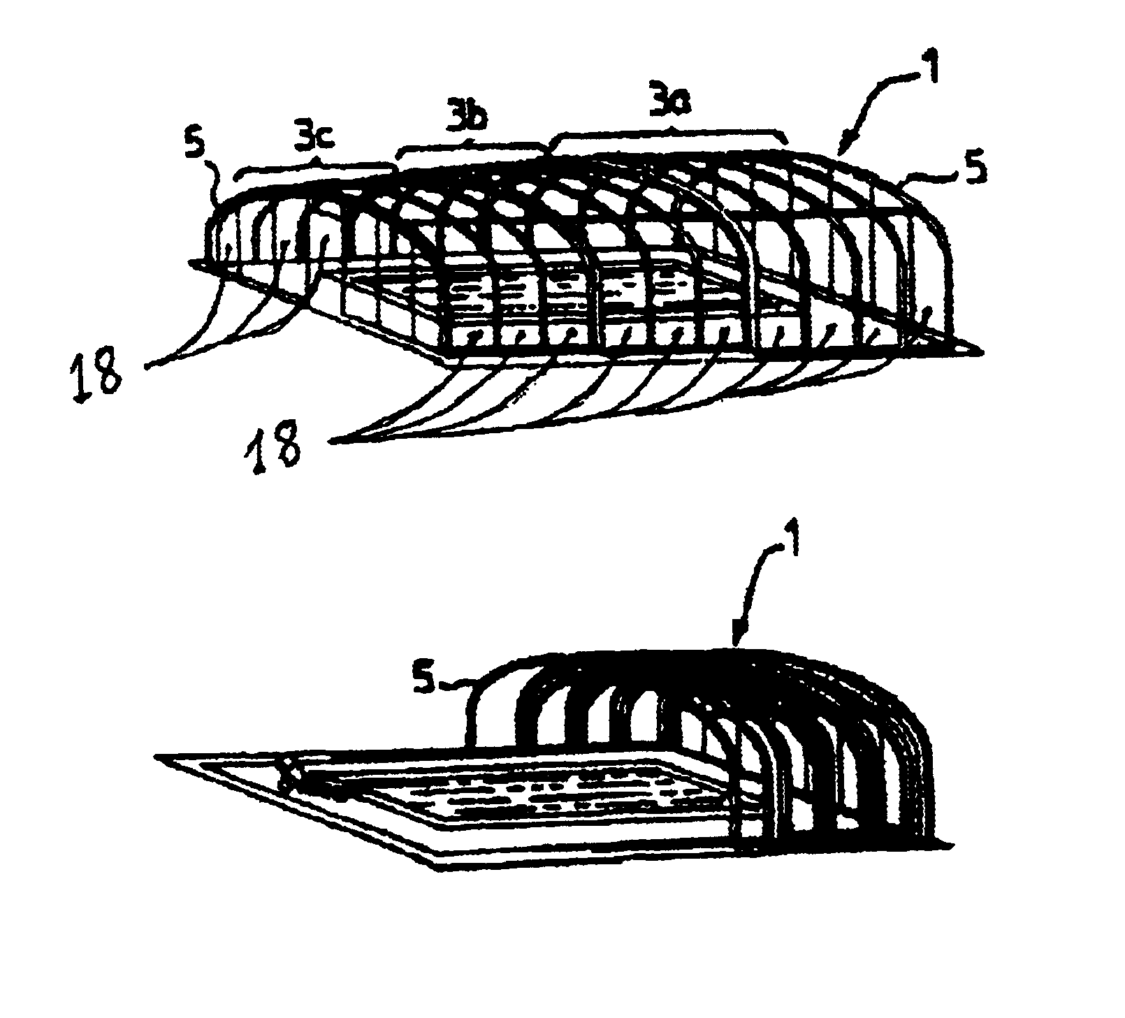
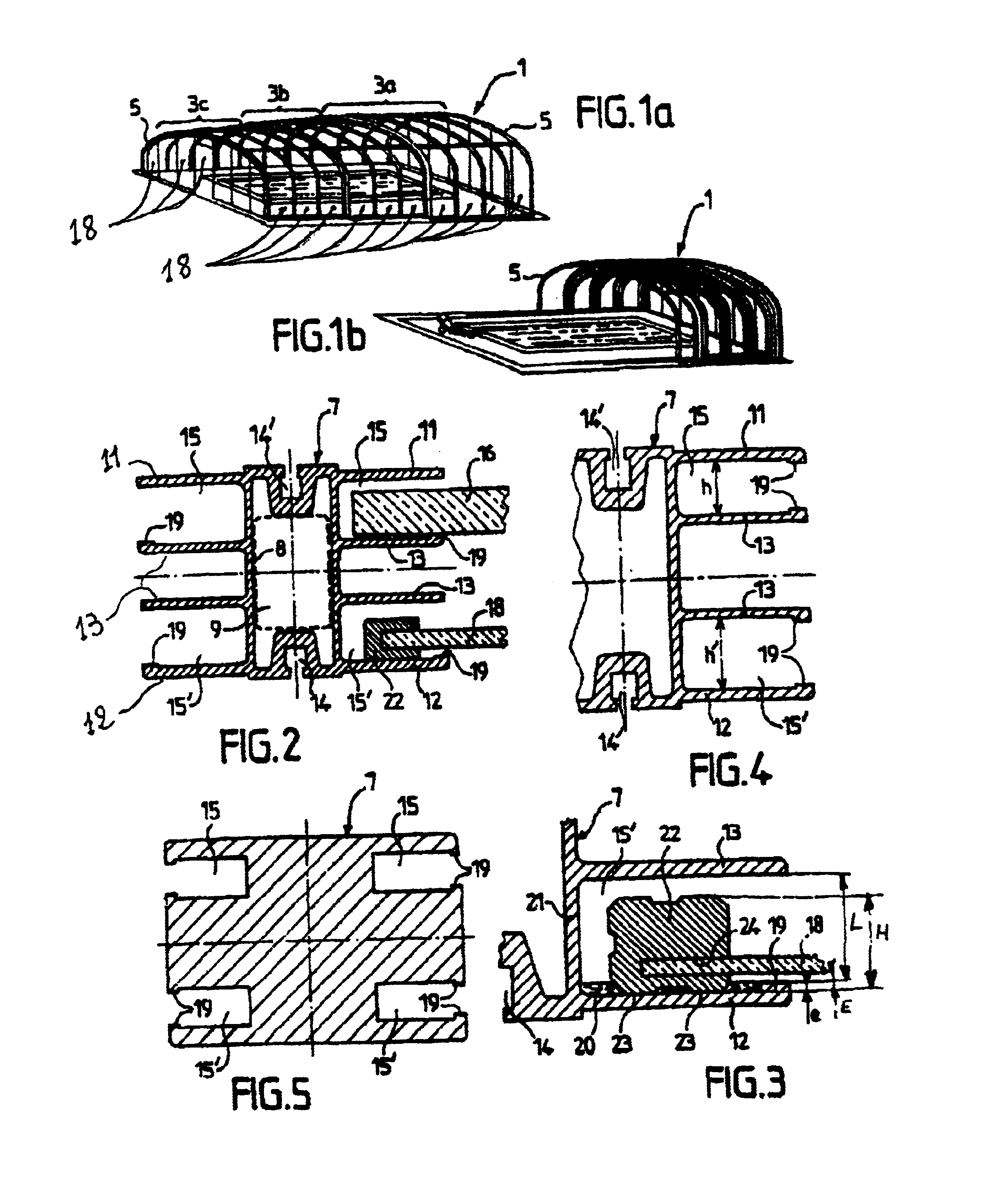
[0029]FIGS. 1a and 1b, which are provided as examples, show a structure 1 used for covering swimming pools, in the closed and open position respectively. This structure consists of three vaults: a fixed vault 3a; a mobile vault 3b, which, when in the open position, is positioned under vault 3a; a third vault 3c, which, when in the open position, is positioned under vault 3b.

[0030]The framework of each of these vaults is of the same type, i.e., it comprises a series of arches 5 that form a certain number of elements.

[0031]Thus, vault 3a is composed of four elements while vaults 3b and 3c are composed of three elements each.

[0032]Each arch 5 is formed by a profile 7, for example, a profile made from extruded aluminum, said profile 7 often being curved in one or several places and sometimes prolonged by vertical parts fitted to the end of the profile 7 in contact with the ground so that more headroom is available under the lateral part of the structure.

[0033]A cross-sectional view of ...


PUM


Abstract

The invention pertains to a covering structure for covering swimming pools, including several pairs of parallel arches that serve to support flexible panels, the arches being made from a curved profile having lateral walls delimiting a series of parallel guide grooves arranged one above another and perpendicularly to a plane of the arch and receiving the panels, and a protective and elevating border disposed on a lateral edge of at least one of the panels contacting at least one of the internal faces of the guide groove, the height of said border being sufficient to prevent the latter from contacting the profile.

Description

TECHNICAL FIELD[0001]The invention presented herein pertains to a retractable covering structure that is particularly intended for covering swimming pools. More specifically, it concerns the profiles used to form the arches that constitute the framework of said structure.BACKGROUND OF INVENTION[0002]It is known that such structures are generally composed of fixed and / or telescopic elements formed by pairs of arches between which panels of a flexible and usually transparent or translucent material are fitted. Some of the panels themselves are maneuverable so that each element may be at least partially uncovered.[0003]Additionally, depending on the desired specifications, the elements themselves may be either fixed or horizontally mobile, sliding into each other in a telescopic fashion.[0004]The arches forming each element are made from a curved, generally enameled-aluminum profile bearing on its lateral faces several grooves designed to support the flexible panels and guide their mov...

Claims


Application Information

Patent Timeline
IPC IPC(8): E04H3/14E04H3/16
CPCE04H3/165Y10S52/17
Inventor LEURENT, GHISLAIN-HENRI
Owner LEURENT GHISLAIN HENRI
Learn More