Dross processing system

a processing system and dross technology, applied in blast furnace details, furnace types, furnaces, etc., can solve the problems of large and complex machinery employed, difficult to conveniently transport to the furnace, and difficulty in removing the material contained, and achieve the effect of compact storage of the dross processing system

Inactive Publication Date: 2000-10-24
Q C DESIGNS
View PDF12 Cites 9 Cited by
  • Summary
  • Abstract
  • Description
  • Claims
  • Application Information

AI Technical Summary

Benefits of technology

FIG. 6 illustrates another embodiment of a dross processing system of the present invention. This embodiment differs from the embodiment of FIGS. 1 and 5 in that the support frame is provided with a platform which supports a spent dross drum and a chain which maintains the drum on the platform. In this embodiment, the drum serves as a spent dross container. The use of a platform to support the spent dross drum and a chain to maintain the drum in position allows the drum to be moved with the system.
FIG. 7 illustrates another embodiment of the present invention which differs from the embodiment of FIG. 6 in that in this embodiment, the drum resides in the support frame, which provides for more compact storage of the dross processing system. The dross processing system is shown where the crucible is in the dross loading position.

Problems solved by technology

The systems have been designed to process large volumes of dross and have employed large and complex machinery, including mixing and pressing equipment to process the dross.
These vessels are generally massive, difficult to transport to the furnace conveniently, or present difficulty in removing the material contained therein.

Method used


Image

  • Dross processing system
  • Dross processing system
  • Dross processing system

Examples


Embodiment Construction

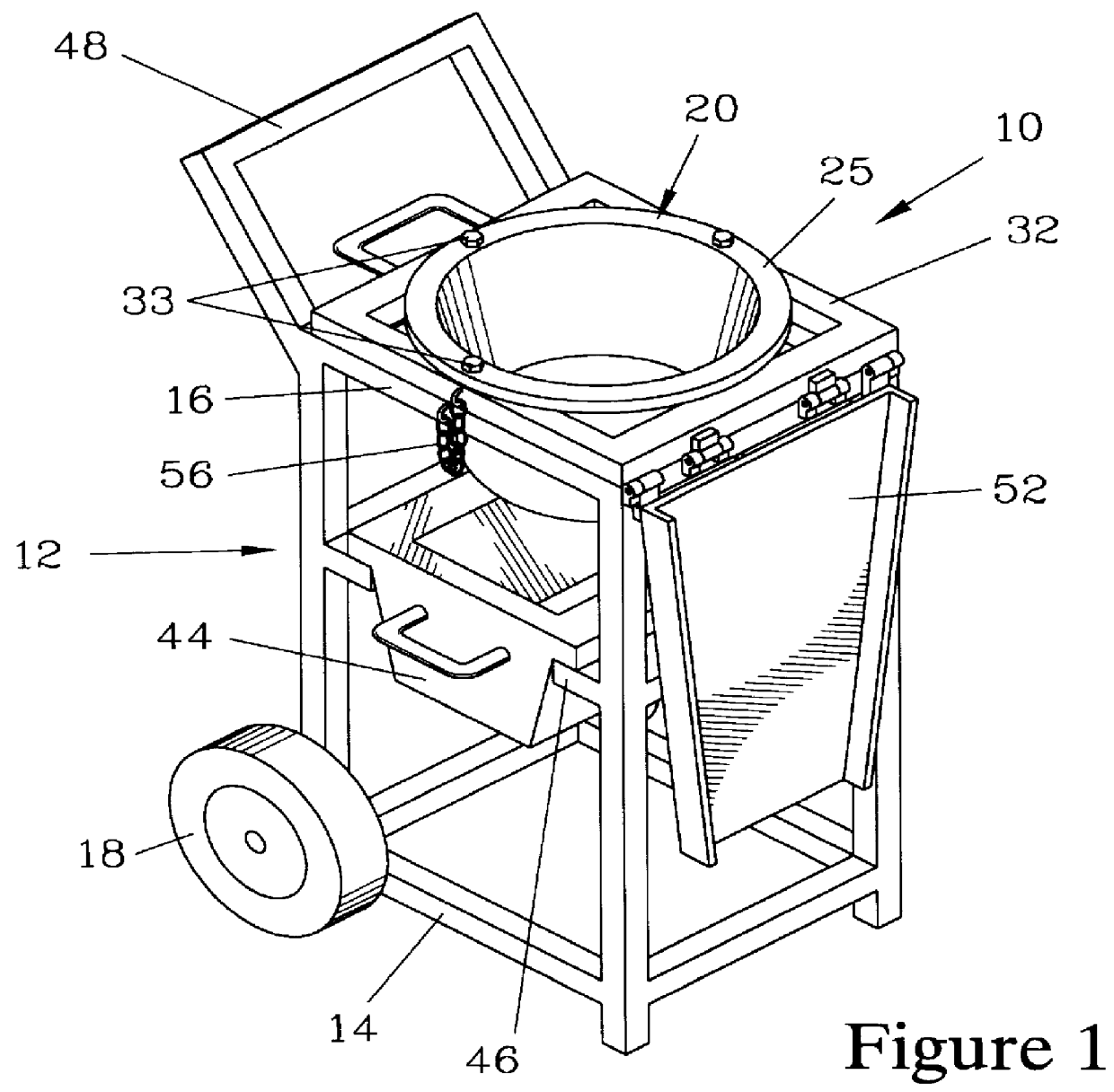
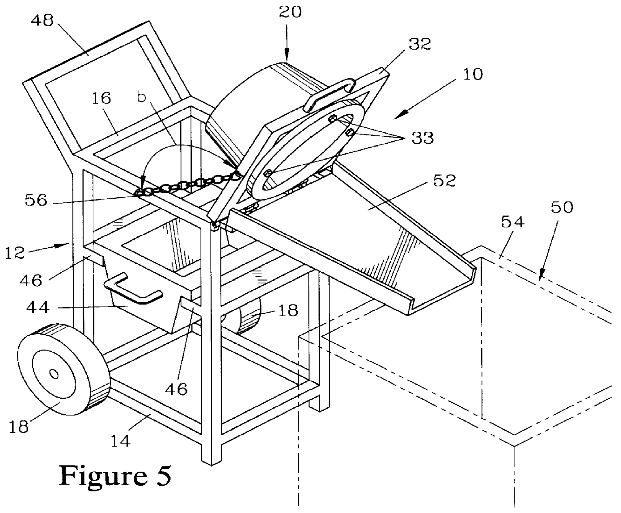
FIGS. 1 through 5 illustrate a dross processing system 10 which forms one embodiment of the present invention. The dross processing system 10 has a support frame 12 having a base 14 and an upper support 16 which is spaced apart from the base 14. A pair of wheels 18 are rotatably mounted to the support frame 12 in the vicinity of the base 14 to facilitate transporting the dross processing system 10 to a furnace site (not shown).

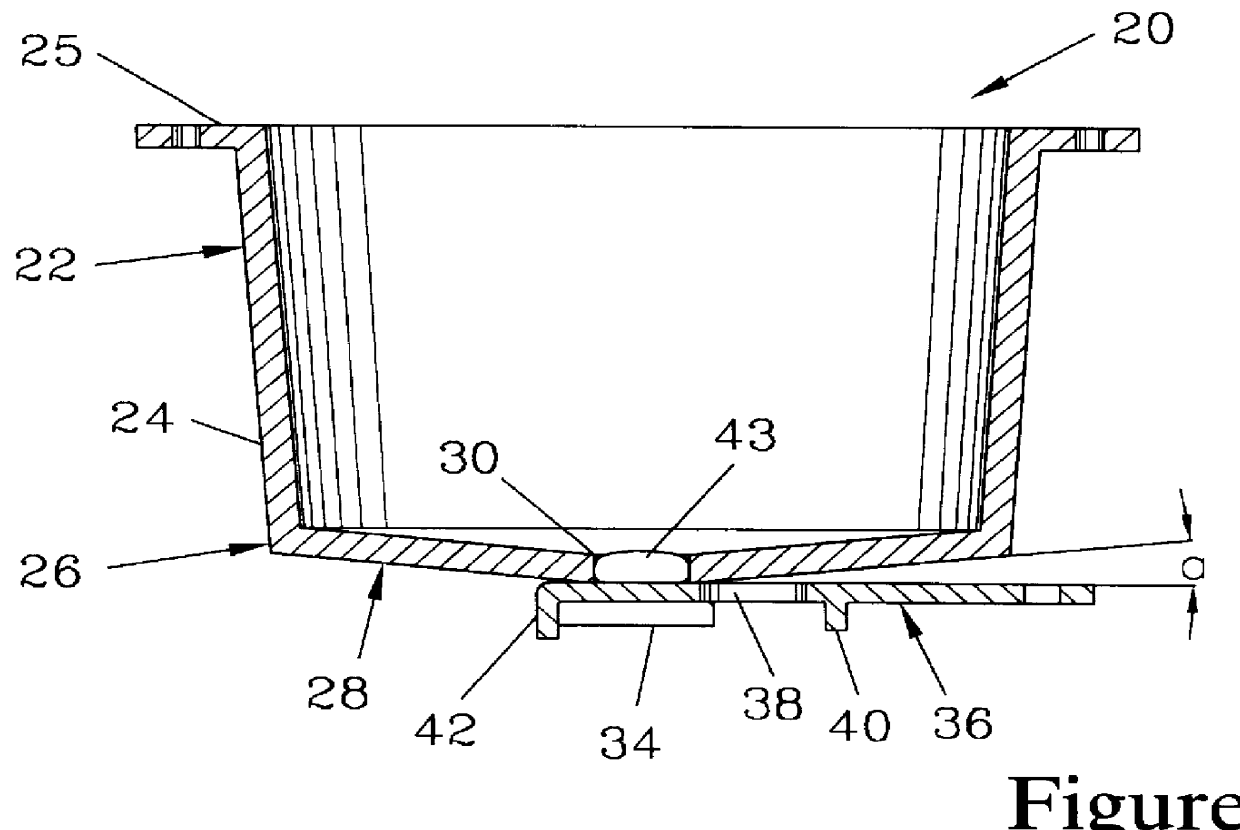
A dross-receiving crucible 20 is provided, which is better shown in the section view of FIG. 2. The crucible 20 has an upper region 22 with a preferably substantially vertical sidewall 24. The upper region 22 terminates in a mounting rim 25. The substantially vertical sidewall 24 may be angled slightly, particularly when the crucible 20 is fabricated by molding. The crucible 20 also has a lower region 26 terminating in a graded bottom wall 28. The bottom wall 28 has a grade of .alpha. which is preferably between about 10.degree. and 20.degree.. A grade helps f...


PUM

PropertyMeasurementUnit
rotation angleaaaaaaaaaa
angleaaaaaaaaaa

Abstract

A portable dross processing system has a support frame with a base and an upper support. A pair of wheels are mounted to the base, and a steering wheel can be pivotably mounted to the base. A dross receiving crucible is mounted in a crucible frame which is pivotably mounted to the upper support. The crucible has a sidewall and a bottom having a port. The crucible may be formed from a mounting rim of steel plate to which a metal mesh reservoir form is attached. The mesh is then covered with moldable refractory cloth, over which a ceramic wash is applied. A finishing wash is applied to the crucible interior. Preheated dross is loaded into the crucible while in a dross loading position. The dross is preferably mixed with an exothermic compound and stirred to promote coalescence of the entrapped metal. After the molten metal forms a pool in the bottom of the crucible, the port is opened to drain the metal. The port can be opened by a closure plate slidably engaging a pair of channels and supporting a port plug. A metal collection pan below the crucible accepts the metal. A handle affixed to the support frame aids in maneuvering the system. The crucible is pivoted to a spent dross removal position to deposit the spent dross into a container such as a drum.

Description

The present invention relates to a dross processing system and a method for operating the same. More particularly, the present invention relates to a method for processing dross and to a portable dross processing system designed to be used on a foundry floor to process in situ the dross generated by a melting furnace, and having particular utility for processing dross from aluminum melting.There a variety of techniques which have been employed to process the dross generated when melting metal in foundries. These dross processing systems are designed to separate metal from the dross, which is a mixture of metal, oxides, and other inclusions. Many of these techniques were developed to treat the dross at a site remote from the furnace. The systems have been designed to process large volumes of dross and have employed large and complex machinery, including mixing and pressing equipment to process the dross. Typical examples of such systems are disclosed in U.S. Pat. Nos. 3,198,505; 4,38...

Claims


Application Information

Patent Timeline
Patent Type & Authority Patents(United States)
IPC IPC(8): C22B7/00C22B7/04
CPCC22B7/04C22B7/004Y02P10/20
Inventor GROTEKE, DANIEL E.
Owner Q C DESIGNS
Why Eureka
Try Eureka