
Retractable device for sun shading suspensory umbrella

a retractable device and umbrella technology, applied in tents/canopies, building types, constructions, etc., can solve the problems of affecting the service life of the umbrella, heavy and difficult to stretch the umbrella, etc., and achieve the effects of long performance life, convenient stretching and closing, and rich aesthetics

Inactive Publication Date: 2005-10-11
XIE JIANYONG
View PDF4 Cites 39 Cited by
  • Summary
  • Abstract
  • Description
  • Claims
  • Application Information

AI Technical Summary

Benefits of technology

[0005]The advantages of the present invention are as follows: 1. The high performance of self-locking by adopting said worm gear and worm structure, not appearing the phenomena of disengage and retroflexion in stretching the sun shading umbrella; 2. Structure tightness, and less mechanical wear, long performance life; 3. Adopting structure of said one worm to drive two worm gears, it is even more convenient to stretch and close by external action, moreover cranking is easiness and labor saving; 4. Said support umbrella rods are composed by two arc-shaped support rods, so that it is rich in aestheticism and can stretch out and draw back freely.

Problems solved by technology

Owing to its huge panel and ribs, a conventional large size sun shading suspensory umbrella used in a beach environment or the like is difficult to control its stretch and closure, so it becomes the key point of using and the selection of umbrella.
There are many defects in said existing structures, such as 1. frictional force is insufficient or not stable, resulting in disengagement or retroflexion in the stretching of sun shading umbrella; 2. frictional force made the abrasion of the parts, impacting its service life; 3. it is heavy and hard to stretch sun shading umbrella by cranking.

Method used


Image

  • Retractable device for sun shading suspensory umbrella
  • Retractable device for sun shading suspensory umbrella
  • Retractable device for sun shading suspensory umbrella

Examples


Embodiment Construction

[0013]Further scope of the applicability of the present invention will become apparent from the detailed description given hereinafter. However, it should be understood that the detailed description and specific examples, while indicating preferred embodiments of the invention, are given by way of illustration only, since various changes and modifications within the spirit and scope of the invention will become apparent to those skilled in the art from this detailed description.

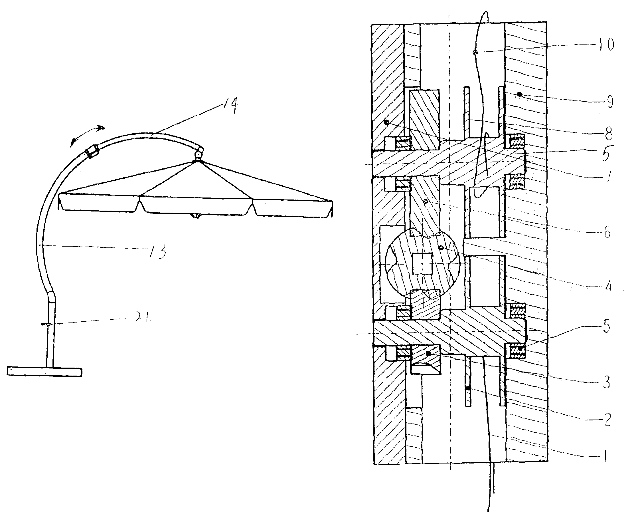
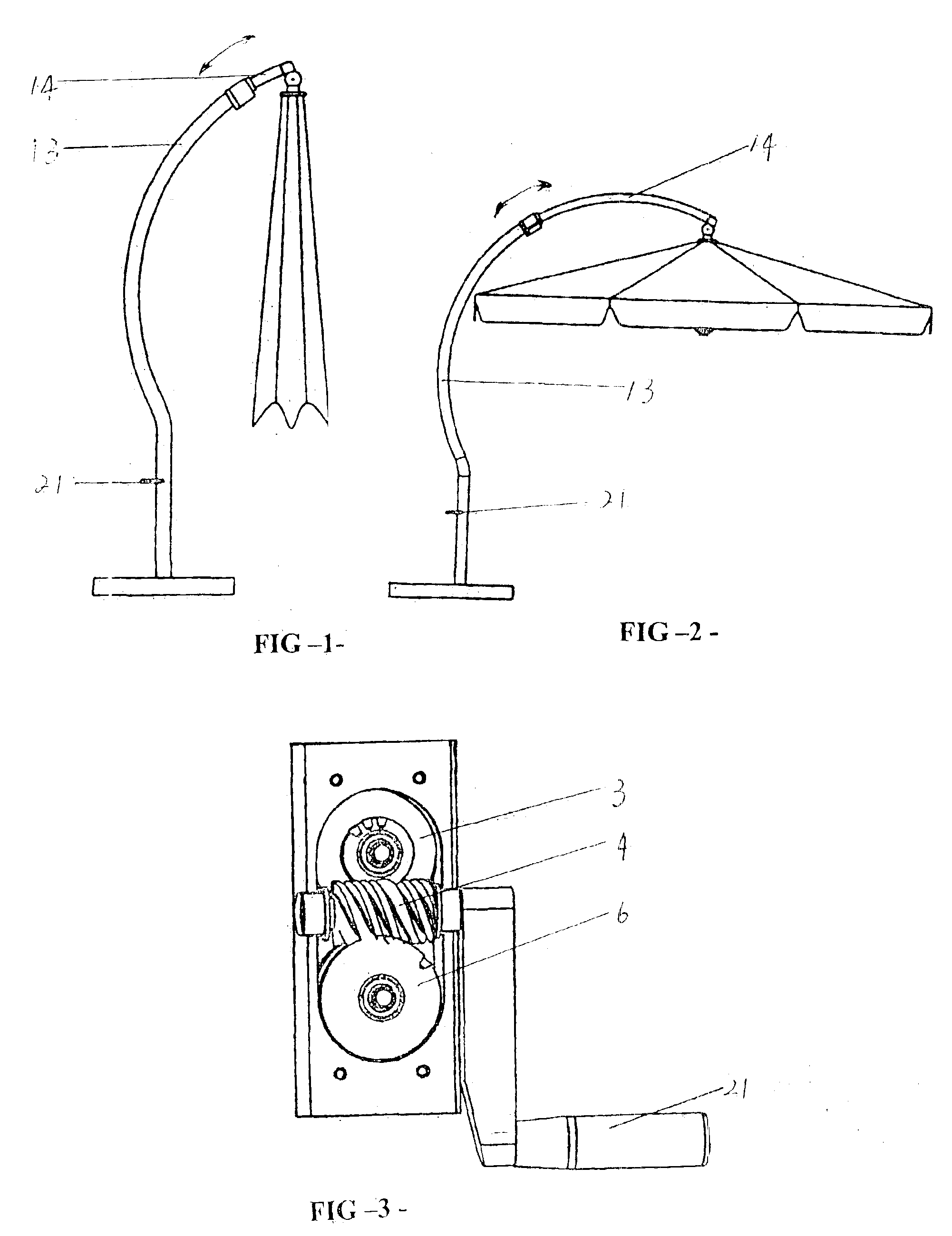
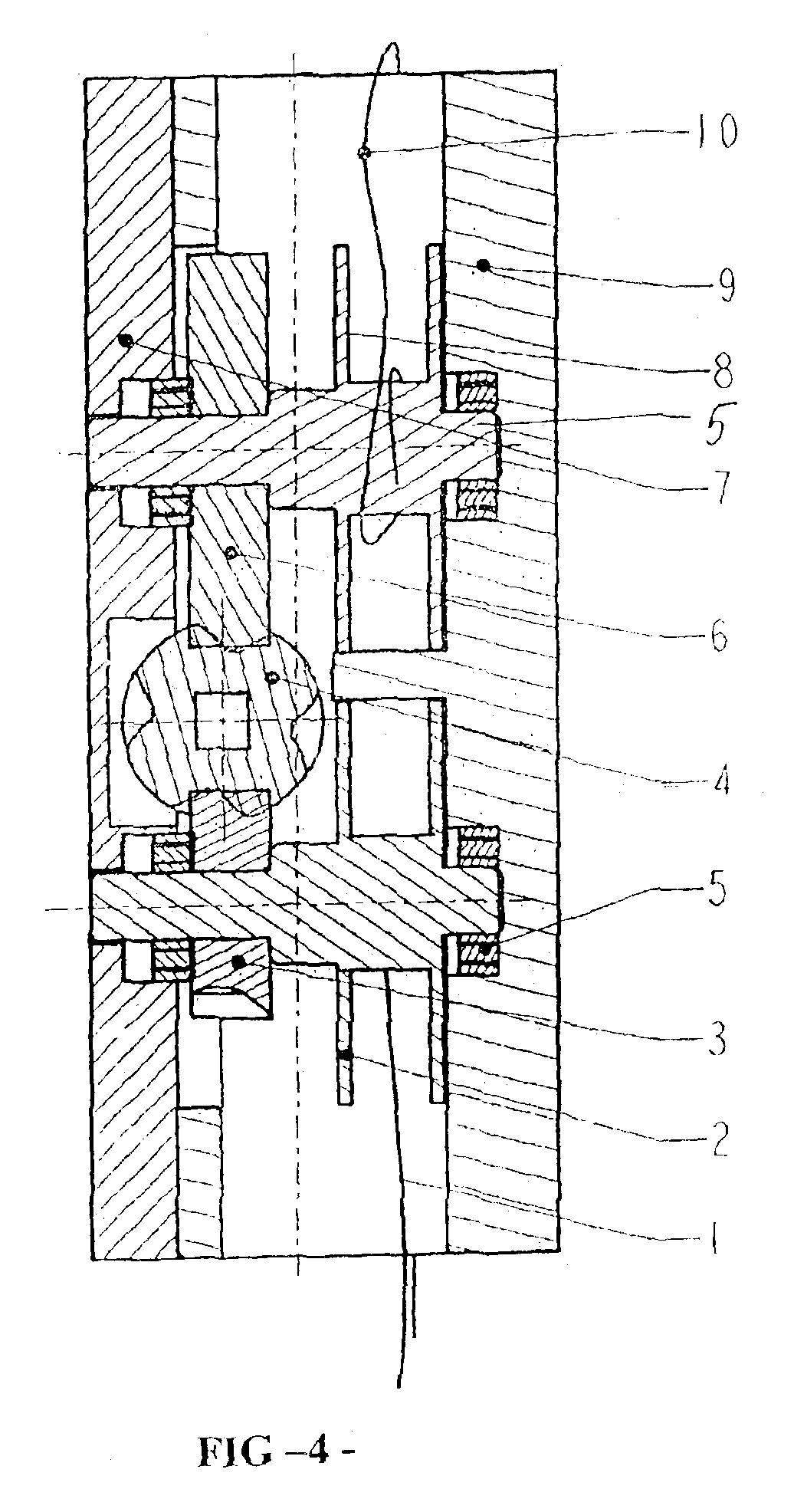
[0014]Referring to FIGS. 1 to 6, the retractable umbrella of the present invention comprises (1) second wire rope, (2) first rotating wheel, (3) active worm gear, (4) worm, (5) axletree, (6) driven worm gear, (7) capping, (8) second rotating wheel, (9) shell, (10) first wire rope, (11) upper support rod assistant slide device, (12) wire rope sheaves, (13) lower support umbrella rod, (14) upper support umbrella rod , (15) protective hood, (16) wire rope feed back pulley, (17) set bolt, (18) lower support rod a...


PUM


Abstract

A retractable device of sun shading suspensory umbrella mainly comprises an upper and lower support umbrella rods, ribs and hand cranking device. The diameter of the upper support umbrella rod is less than the lower support umbrella rod. The upper umbrella rod is located within the low portion of the retractable device. The hand cranking retractable device is equipped within lower portion of the lower support umbrella rod. The hand cranking retractable device is a worm with a handle, which connects with an active worm gear and a driven worm gear separately on both sides. The active worm gear and driven worm gear separately connects to entwined wire rope first rotating wheel and second through axletree. One end of the first wire rope is wired to first rotating wheel. The other end is securely mounted to lower umbrella tray. One end of the first wire rope is wired to second rotating wheel, the other end of said second wire rope is securely mounted to upper support umbrella rods. The advantages include high performance of self-locking by adopting the worm gear and worm structure, and avoiding the phenomena of disengage and retroflexion in stretching the sun shading umbrella.

Description

FIELD OF THE INVENTION[0001]The present invention relates to a retractable device for outdoor umbrella, and more particularly, to an improved retractable device of stretch and closure for large size sun shading suspensory umbrella used in a beach environment or the like.BACKGROUND OF THE INVENTION[0002]Owing to its huge panel and ribs, a conventional large size sun shading suspensory umbrella used in a beach environment or the like is difficult to control its stretch and closure, so it becomes the key point of using and the selection of umbrella. Various of stretch and closure structures of umbrella are available in the umbrella making field, but all existing structures of hand cranking device are in a model of ratchet and pawl. The solution of the stretch and closure structures of umbrella is mainly laid to frictional force. There are many defects in said existing structures, such as 1. frictional force is insufficient or not stable, resulting in disengagement or retroflexion in th...

Claims


Application Information

Patent Timeline
Patent Type & Authority Patents(United States)
IPC IPC(8): A45B25/14A45B23/00A45B25/00A45B19/04A45B19/00
CPCA45B23/00A45B25/14A45B19/04A45B2023/0012A45B2023/0037A45B2023/0062A45B2025/146
Inventor YU, FENGMING
Owner XIE JIANYONG
Features
  • Generate Ideas
  • Intellectual Property
  • Life Sciences
  • Materials
  • Tech Scout
  • Unparalleled Data Quality
  • Higher Quality Content
  • 60% Fewer Hallucinations
Learn More