Subterranean well completion incorporating downhole-parkable robot therein

a technology of subterranean wells and robots, which is applied in the direction of borehole/well accessories, survey, instruments, etc., can solve the problems of limited sensing and reacting capabilities, increase the cost of completion, and reduce the operational reliability of completions, so as to facilitate the substantially permanent positioning of robots

Inactive Publication Date: 2005-10-11
HALLIBURTON ENERGY SERVICES INC
View PDF15 Cites 72 Cited by
  • Summary
  • Abstract
  • Description
  • Claims
  • Application Information

AI Technical Summary

Benefits of technology

[0011]In order to facilitate the substantially permanent positioning of the robot within the subterranean well completion, the robot is given a configuration which, at the location of the robot within the tubular structure, laterally blocks no more than about eighty percent of the flow area of the tubular structure, thereby facilitating continuing fluid flow past the robot through the interior of the tubular structure. In one embodiment of the robot it has a tubular, open-ended both that permits well fluid to flow both through and around the robot.

Problems solved by technology

Conventional subterranean well completions used to flow selected subterranean fluids, such as oil and gas, to the surface typically are relatively passive systems with only limited capabilities for sensing and reacting to changes in downhole conditions.
This requires the running of hydraulic and / or electrical control lines to the actuators of the valves and other well tools—a requirement which correspondingly increases the cost of the completion and reduces its operational reliability.
Moreover, downhole repair and modification also typically require costly and time-consuming physical intervention into the completion.

Method used


Image

  • Subterranean well completion incorporating downhole-parkable robot therein
  • Subterranean well completion incorporating downhole-parkable robot therein
  • Subterranean well completion incorporating downhole-parkable robot therein

Examples


Embodiment Construction

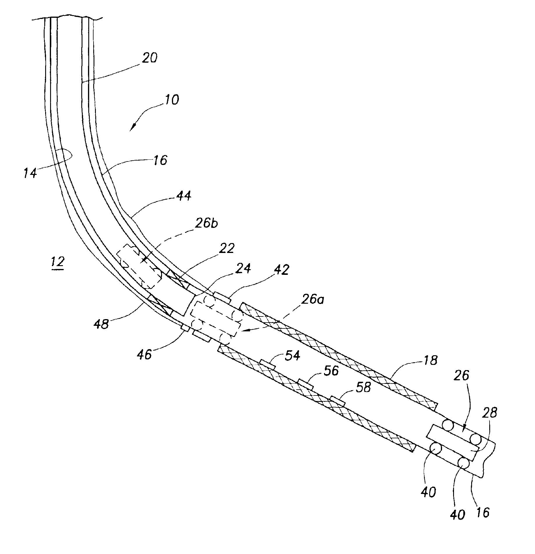
[0034]Cross-sectionally illustrated in schematic form in FIG. 1 is a subterranean well completion 10 that extends through the earth 12 and embodies principles of the present invention. In the following description of the well completion 10 and other apparatus and methods described herein, directional terms, such as “ab ove”, “below”, “u pper”, “lower”, etc., are used only for convenience in referring to the accompanying drawings, Specifically, the term “ab ove” is used herein to designate a direction toward the earth's surface along a wellbore, and the term “below” is used herein to designate a direction away from the earth's surface along a wellbore, even though the wellbore may not be substantially vertical. Additionally, it is to be understood that the various embodiments of the present invention described herein may be utilized in various orientations, such as inclined, inverted, horizontal, vertical, etc. and in various configurations, without departing from the principles of t...


PUM


Abstract

A subterranean well completion has a tubular structure in which a remote controlled robot is permanently disposed. The robot is self-propelled, programmable, receives instructions from and communicates data to the surface, and is adapted to receive power from a downhole source and perform a variety of well tasks such as, for example, positioning valves and other well tools and sensing the values of predetermined downhole parameters and relaying the sensed information to the surface. The robot, which is operable without physical intervention through the tubular structure to the robot, propels itself to a location in the tubular structure at which a desired well task is to be performed, performs the task and then parks itself in the tubular structure until another well task is to be performed by the robot.

Description

CROSS-REFERENCE TO RELATED APPLICATION[0001]This application is a continuation-in-part of U.S. application Ser. No. 10 / 174,675 filed on Jun. 19, 2002 now U.S. Pat. No. 6,799,633, and entitled “DOCKABLE DIRECT MECHANICAL ACTUATOR FOR DOWNHOLE TOOLS AND METHOD”, such prior application being incorporated by reference herein in its entirety.BACKGROUND OF THE INVENTION[0002]The present invention generally relates to subterranean well completions and associated operations performed therein and, in a preferred embodiment thereof, more particularly relates to a subterranean well completion incorporating therein a parkable robot which is capable of performing a variety of operations in the well completion, communicating with and receiving instructions from the surface, and receiving power from a downhole source.[0003]Conventional subterranean well completions used to flow selected subterranean fluids, such as oil and gas, to the surface typically are relatively passive systems with only limi...

Claims


Application Information

Patent Timeline
IPC IPC(8): B23K3/06E21B34/00E21B23/03E21B23/00E21B34/14
CPCB23K3/0623E21B23/00E21B23/03E21B34/14G01V11/002E21B2023/008E21B23/001
Inventor ROSS, COLBY MUNROTHURMAN, ROBERT L.HAMID, SYEDWOHLEB, JR., CLIFFORD DAVIDMCGREGOR, RONALD W.
Owner HALLIBURTON ENERGY SERVICES INC
Why Eureka
Try Eureka